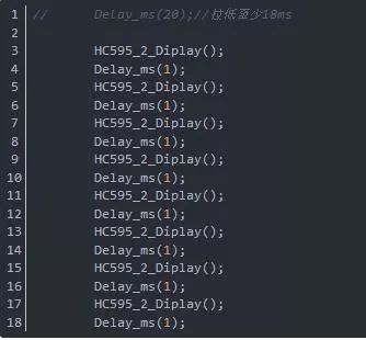
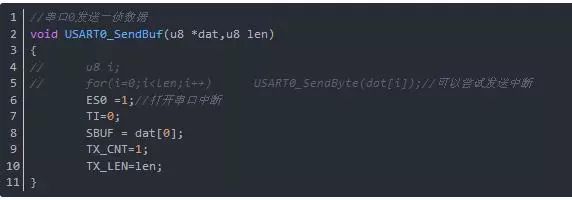
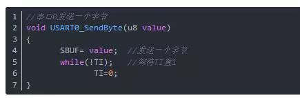
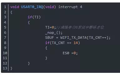
I don't know how everyone came to study 51, anyway, I flicked all the way. Nowadays, using 51 to develop products must fully use its internal resources. Originally, the main frequency and resources are not as good as 32. How can we develop good products without full use? Then today I learned two small skills: extension Time and serial port transmission interrupt The situation is like this. In the development of the product, I encountered 74HC595 control digital tube. Everyone who has used this digital logic chip knows that one digital tube is okay. If there are more than one, it must be refreshed continuously. Then achieve the effect of displaying different broken codes (numbers) in different bits. This refresh rate is still very particular. I don’t know if my theory is correct. Anyway, I know that the light bulb is constantly flickering when the 50Hz civil electricity is connected to the light bulb. Then based on this principle, I just need to ensure that the display is refreshed once in time at a frequency above 50 Hz (within 20ms). However, the actual effect is that I can almost not see the strobe after a 5ms refresh time. The delay is the software for loop delay, which is not accurate, but it is almost the same. I don't understand why it takes 5ms to eliminate the flicker. Anyway, just follow the actual effect. The problem is, the 5ms periodic refresh, is it that the MCU simply refreshes the digital tube and does not do other work, which is often impossible. The method I implemented during debugging is like this: The program does not have an operating system, it is just an ordinary while loop. There are many tasks in a loop, and it may take a long time to run. Then I will copy a few more refresh functions and place them in different positions according to the approximate time consumption of the tasks. In this way, the result is quite obvious, at least the effect is much better. Then there is a new problem. When a task function executes for a long time, there will still be flickering. Some friends may think that putting a refresh display function in the task function is indeed a good way. I also used it in the program. However, some task functions have strict requirements on time, and they really cannot be placed inside to interfere with its underlying driver. The point is here, I will record the two methods I use; 1. Clever use of the delay function of the task function itself For example, I used the DHT11 temperature and humidity sensor in the project. This sensor (including DS18B20) is a single-bus protocol and has a very strict time requirement. I looked at the underlying driver and found a relatively long time: The above picture is the timing diagram of DHT11. The place marked by the red line is the actual signal from the MCU to the sensor. The manual here says that it is pulled down at least 18ms, so I will make an article here. The following is the code I modified: Just let this 20ms time to do something else, which is to refresh the digital tube. Of course, if there is an operating system, the delay invocation mechanism of the operating system will further improve efficiency. Here, just make sure that the execution time in the red box is similar to the time required to delay, and that the sensor data can be read normally. I also estimated that there is no actual test time. After all, it is not convenient for simulation and it is not at the company's hand. No oscilloscope. 2. The use of serial port sending interrupt In addition to the delay time modification here, there is another tricky place, that is, the serial port sends one frame of data, and one frame of data is relatively long. It takes too much time to wait for the sending of bytes one by one, and it is not easy to add. What to do with the refresh function, I suddenly thought of the serial port sending interrupt that I used before. So I checked the register and tried it out, and it was really ok. It means that the sending interrupt of the serial port has not been used before, and the receiving interrupt has been used at most. The code before and after modification is as follows: The note is that the bytes are sent in order of number of bytes. The function prototype for sending one byte is as follows: Modified serial port interrupt function: From the structure of the code, the general principle is that the serial port interrupt is closed when there is no data to send. When there is data to be sent, first prepare the data and store it in an array, and then call the sending function. The content of the sending function is to open the interrupt of the serial port (ES=1), clear the sending completion flag (TI = 0), put the first data to be sent into the register (SBUF = dat[0]), and put The simulated sending data address points to the second byte sent (because the first one has already been sent), and then just wait for the interrupt. Every time a byte is sent, the serial port will enter the interrupt function. In the interrupt function, first judge whether it is a sending interrupt (the sending interrupt and receiving interrupt of the 51-core serial port use the same interrupt vector). Make sure to clear the interrupt after sending the interrupt. Mark, and then continue to put the next data to be sent (SBUF = WIFI_TX_DATA[TX_CNT++];) and the data address to be sent is shifted back. Judge whether all the data to be sent has been sent, and then close the serial port interrupt after sending. In this way, one frame of data is sent perfectly and the efficiency is improved! The above method is just a simple process, the detection length is a fixed length of 14 bytes, if it is an indefinite length detection, it can be modified according to the actual situation. There is another problem that I haven't dealt with here but need to pay attention to, that is, there is a situation that needs to be considered, when a frame of data has not been sent, a new frame of data needs to be sent. In this case, the storage method needs to be modified. A note here, the solution is to store the data that needs to be sent into a relatively large array, and then assign two pointers to this array, namely the head pointer (p) and the tail pointer (q), each time you send First judge whether it is (p=q) If it is, it will prove that the previous data has been sent, and now it can be unimpeded; if they are not equal, continue to store and move the position of the tail pointer q back at the same time (if it overflows, then Just go back and chant—the way to loop an array). Nintendo WII U Console Adapter This WII Uadapter is factory supply with cheap price and high quality, we provide US EU UK Plug, for the UK plug, we also can do fused plug to protect your charger better.
Nintendo WII U Adapter, Nintendo WII U Console Charger, Nintendo WII U Adaptor, Nintendo WIIU AC Charger, Nintendo WII U Power Supply Shenzhen GEME electronics Co,.Ltd , https://www.gemesz.com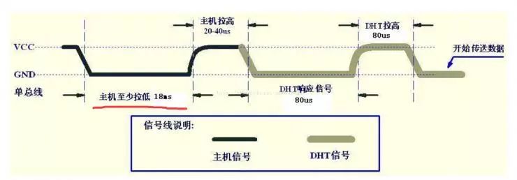
Product Features:
➤ Top quality replacement power adapter for Nintendo Wii U Console(With automatic voltage function)
➤Output: 15V 5A;Simple plug and play setup, allow you to charge and play at the same time from up to 7 ft away.
➤ It supports to use both AC 110V and AC 220V, which avoids the defect of using AC 110V only with original Nintendo adapter.
Product Specifications:
- Color: Grey
- Input: AC 100-240V
- Output: DC 15V5A


- Cable Length: Approximate 90cm (Wall plug side to AC adapter), Approximate 100cm (Console side to AC adapter)