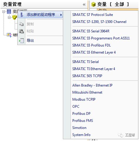
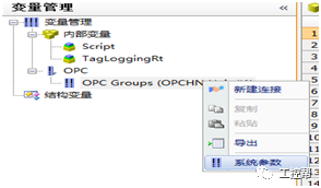
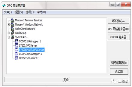
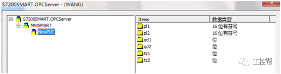
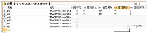
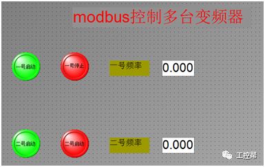
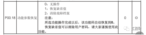
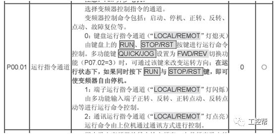
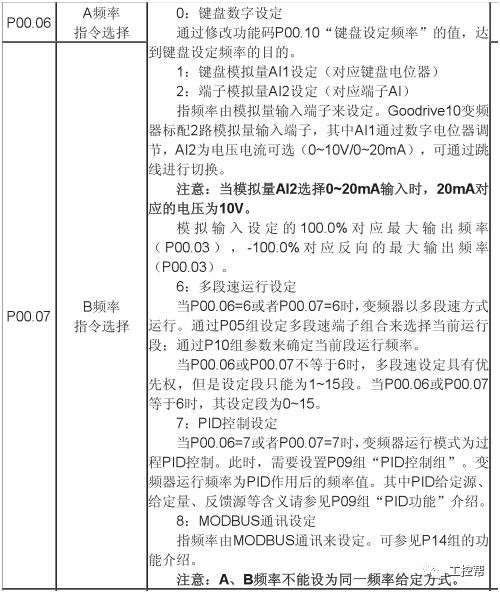
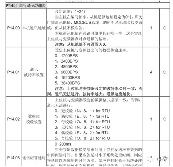
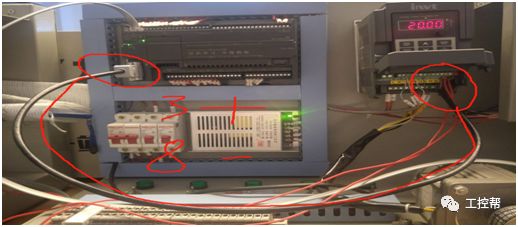
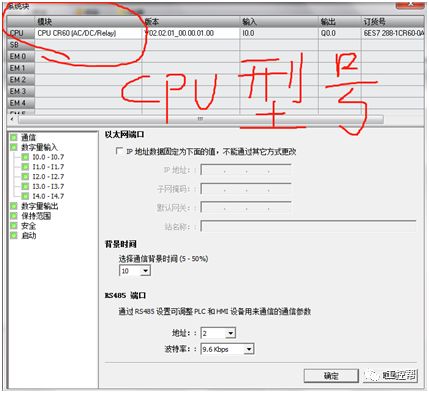
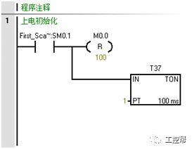
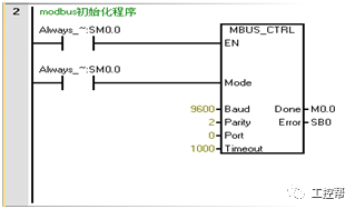
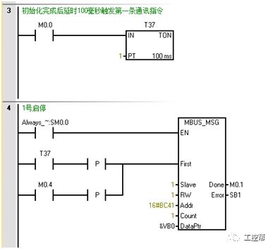
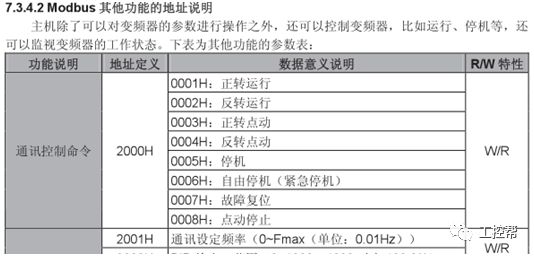
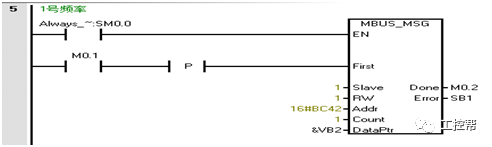
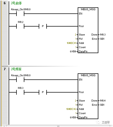
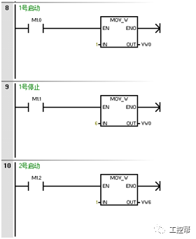
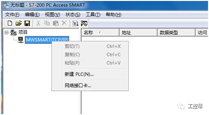
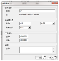
Hello everyone, I was an amateur in industrial control, my name is Wang Jiayang. When I came into contact with Siemens PLC programming at work, I learned a little about it by self-study after work, but many places cannot be completed independently, and the knowledge points I learned cannot be integrated into a piece, so I found a professional training institution to learn systematically. Thought, after learning about Industrial Controls from the Internet, I made up my mind to ask for leave to study. After reporting my ideas to the company, the company leaders were very supportive, not only approved my leave, but also subsidized me to learn and improve my skills. Siemens general classes, including Siemens S7-200 SMART basic class and 300/400 Botu advanced class. Now I have completed the SMART basic class. After a month of study, I have a comprehensive understanding of SMART. The step-by-step learning from the shallower to the deeper is very suitable for beginners. The following advanced applications are also explained very comprehensively. The next step is to enter the 300/400 study. Use the weekend to show you my learning results, and share an example of using wincc to realize the Ethernet communication with smart to control the modbus communication between SMART and the inverter. 1. First, we need a 200smart plc, a 485 interface, 2 1.5 square cables, a network cable, 2 inverters, and a computer. 2. Here I use two INVT inverters, and connect the 485 communication terminals of the two inverters to positive and negative to negative, and connect them to the 3rd and 8th pins of the PLC485 interface (3 positive, 8 Negative), use a network cable to link the PLC and the computer. As shown: 3. After the hardware connection is completed, we start to write the communication program: 1: Hardware configuration (only realizes the communication function, does not consider the power-off retention, so there is no setting). 2: Write the program: The first step: power-on initialization procedure. Step 2: Call MODBUS library to initialize communication. Step 3: Use the initialization completion bit M0.0 to delay 100ms to trigger the first communication instruction. The content is: write the value of vw0 to the address of station 1 as the 2000H register (2000H is hexadecimal and needs to be converted to decimal and added 40001 is then converted to hexadecimal to get 16#BC41). The following figure shows the communication register address list of the inverter. The value in vw0 is 0001-0008 and corresponds to its corresponding function. 2001H is the frequency address converted into hexadecimal address as BC42 The following figure shows frequency setting No. 1: write the value of vw2 into 2001H. The procedure of station 2 is the same as that of station 1. As shown: Then the following program is the control: because the decimal number 1-8 is the same as the hexadecimal number, I didn't write 16#. After the program is written, it is downloaded to the PLC. Step 4: Create a project with PC ACCESS SMART. Create a new PLC and set its address to 192.168.2.1, and then create variables as shown below: Then click Save. Step 5: Open winccv7.3 to create a single user project. Right-click the variable management, select OPC in the variable management Select system parameters. Click Browse Server Add the variable created in PC ACCESS to WINCC. After successful addition, calibrate the AS-OS values ​​of PL1 and PL2. Then create a new screen in the WINCC graphics editor, as shown below: Set the parameters of each graph and link it to the corresponding variable, save and click to activate. 4. Adjust the parameters of the inverter. Initialize its parameters first. Then set P00.01 is 2 P00.06 is 8 Adjust the communication parameters: P14.00: The address of No. 1 inverter is 1, and the address of No. 2 is 2. P14.01: 3 The baud rate is 9600. P14.02: 1 even check one stop bit. Other parameters default. After the setting is completed, the start, stop and frequency of the two inverters can be controlled in wincc. Up to 32 inverters can be controlled simultaneously. Original Bulb Lamp With Housing The original projector bulb lamp with housing is installed with the original brand factory projection lamp, providing bright and clear pictures, visual appreciation, high quality and worry-free service. It can be directly put into the projector, the installation is simple, and no reassembly is required. Original Bulb Lamp With Housing,Buy Projector Lamp,Projector Lamp Light,Original Projector Shenzhen Happybate Trading Co.,LTD , https://www.happybateprojector.com

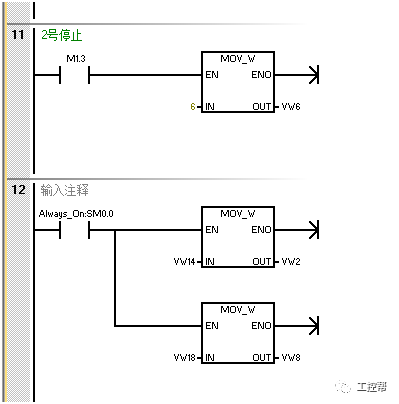
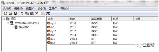
 Create M1.0 to M1.3 and vw14 vw18 in sequence. As shown below