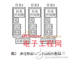
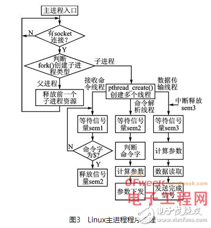
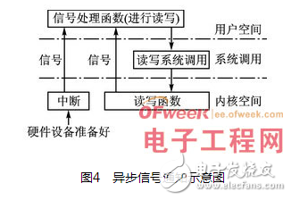
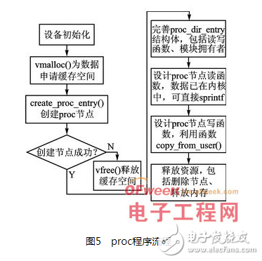
In the past few years, Linux has successfully replaced some of the most important traditional RTOS (real-time operating system) platforms and has become the preferred embedded operating system for a variety of embedded devices and applications. Although once considered an unimportant platform, today embedded Linux has become the mainstream, widely used in consumer electronics, handheld and wireless devices, data networking, and telecommunications equipment. The Android mobile phone operating system released by Google in November 2007 is an operating system based on the Linux kernel, enabling Linux to achieve leapfrog development in the digital mobile phone industry. The author realized the application transplantation of RTOS to Linux in the project research and development from desktop spectrum analyzer to handheld spectrum analyzer. This article introduces the overall design ideas and implementation details of some key issues. Almost all RTOSs have a simple programming model, which consists of multi-threaded execution (usually called tasks), contained in a single address space. In RTOS, multiple tasks run at the same time under a single main program, which has a high real-time response capability. In the past, most embedded processors did not have a memory management unit, so RTOS is a single address space mode, that is, their physical and logical addresses are the same. However, most mid-to-high-end processors are currently equipped with MMU (Memory Management Unit). With the support of MMU, Linux uses virtual memory management to divide the address space into physical addresses and virtual addresses. Therefore, the system must perform address mapping when operating the hardware. According to the architecture of the two types of systems, the basic framework of RTOS porting to Linux is shown in Figure 1. As can be seen from Figure 1, the basic steps of transplantation are: â‘ All application codes of RTOS are transplanted to a single Linux process; â‘¡ Convert RTOS tasks into Linux threads; â‘¢The physical address space of RTOS is mapped to the virtual address space of Linux. In the process of specific application transplantation, consideration should also be given to solving the real-time response of the upper application to the underlying hardware interrupt, the asynchronous communication and data exchange between the application layer and the kernel layer, and the design of multi-process and multi-thread under the Linux system. 2.1 Address mapping For the current MMU-containing processors, the Linux system provides a complex storage management system that enables the virtual memory that the process can access to reach 4GB. In the Linux system, the 4GB virtual memory space of the process [1] is divided into two parts-user space and kernel space. The user address space is generally distributed from 0 to 3GB, and the remaining 3 to 4GB is the kernel space. Upper-layer applications can only access virtual addresses in user space, but cannot access virtual addresses in kernel space. The application program can access the kernel space only through system calls (on behalf of the application process execution in the kernel mode) and other methods. The peripheral I/O resources are not in the Linux kernel virtual address space (such as SRAM or hardware interface registers, etc.). If you need to access a peripheral I/O resource, you must first map its physical address to the kernel virtual address space , And then you can access it in the kernel space. There are two ways for the Linux kernel to access peripheral I/O resources: static mapping (map_desc) and dynamic mapping (ioremap). For static mapping, the kernel statically creates a linear mapping table (ie pagetable) from I/O resources to the kernel address space through the map_desc structure during system startup. This mapping table is a one-to-one mapping relationship. Developers can customize the virtual address after the mapping of the I/O memory resource. Once the static mapping table is created, there is no need to perform ioremap mapping when accessing the I/O resource in the kernel or driver, and it can be accessed directly through the mapped I/O virtual address. The more commonly used dynamic mapping methods are mainly discussed here. The dynamic mapping method is to dynamically create a mapping table from peripheral I/O memory resources to kernel virtual addresses directly through the ioremap function provided by the kernel, so that this section of I/O resources can be accessed in the kernel space. code show as below: #definebcon*(volaTIleunsignedlong*) ioremap(0x56000010, 4)//Dynamic mapping The meaning of the above code is to map the 4-byte physical address starting at 0x56000010 to the virtual address of the kernel, and the returned starting virtual address value is assigned to the bcon macro definition. The operation on the macro definition is the operation on the physical address. The ioremap macro is defined in asm/io.h: #defineioremap(addr, size)__ioremap(addr, size, 0) The prototype of __ioremap function is (arm/mm/ioremap.c): void__iomem*__ioremap(unsignedlongphys_addr, size_tsize, unsignedlongflags); Among them, phys_addr is the starting I/O address to be mapped; size is the size of the space to be mapped; flags is the flags related to the I/O space to be mapped and permissions. This function returns the mapped kernel virtual address (3G~4G), and then you can access this section of I/O memory resources by reading and writing the returned kernel virtual address. Therefore, at the beginning of the migration, the device physical address mapping should be completed in the header file to facilitate subsequent development. 2.2 Multi-process and multi-threaded design Most RTOS kernels provide a multitasking management mechanism. A task is a running activity of an infinite loop program segment with independent functions, and is a unit of real-time kernel scheduling. Multi-tasks are executed in parallel under the management and scheduling of the kernel, and the tasks are infinite loops, and continue to realize their functions. A schematic diagram of a multi-task real-time operating system is shown in Figure 2. After comparing the architectures of the two types of embedded systems, the process of transplantation naturally converts the multitasking of RTOS into multi-process and multi-threaded Linux. A process is the smallest unit of Linux system resource management, an execution process of a program, and the basic unit of Linux resource allocation. Thread is inside the process, it is the basic unit that is smaller than the process and can run independently, and it is the basic unit for the Linux system to allocate CPU time. Threads save resources and time more than processes. In the specific transplantation process, the main process is used to wait for the upper-layer connection, and the main process is executed in parallel by multiple threads. At the same time, mutual exclusion semaphores are used to solve the synchronization problem of thread access to resources. The Linux main process program flow is shown in Figure 3. 2.3 Application layer and kernel layer communication Because RTOS's single address space mode makes its kernel layer and application layer no different, it has certain advantages in data exchange and real-time response. The Linux system provides a strict memory management mechanism to ensure that the system runs more stably. But at the same time, it increases the difficulty of communication between the application layer and the kernel layer, as well as the application layer and the underlying hardware. This section mainly solves the two key issues of signal notification and data exchange between the application layer and the kernel layer. 2.3.1 Asynchronous signal notification mechanism RTOS is a system that can react to external events within a limited time. In RTOS, time is an important system resource, and the response to external events and the execution of tasks must be completed within a limited time. In a multi-machine system, the sending and receiving of messages must also be completed within a limited time. In RTOS, the correctness of the output result depends not only on the end of the logic formed by the calculation, but also on the time when the result is generated. Linux was not originally defined as a real-time operating system when it was released. With the continuous development of the Linux kernel, the stable Linux2.6 kernel now has a good real-time response capability. In the research project of this article, the upper-layer application needs to respond to the underlying hardware in real time. RTOS does not strictly distinguish between upper-layer applications and kernels. Its multi-task parallel execution can achieve the purpose of real-time response very well. When ported to a Linux system, upper-layer applications and lower-layer hardware cannot communicate directly, but must pass through the kernel driver layer. Although it can be implemented in a query mode, the real-time performance is not high, and CPU resources are wasted at the same time. This article adopts the asynchronous signal notification mechanism to realize the real-time response of the upper-layer application to the underlying hardware. Asynchronous notification [2] means: once the device is ready, the application is proactively notified, so that the application does not need to query the status of the device at all. This is very similar to the concept of "interrupt" on the hardware. The more accurate name is "signal driven". Asynchronous I/Oâ€. The signal is a simulation of the interrupt mechanism at the software level. In principle, the signal received by the process is the same as the interrupt request received by the processor. The signal is asynchronous, a process does not have to wait for the arrival of the signal through any operation, the principle is shown in Figure 4. In the specific program design process, in order to process the signal released by a device, the upper application must complete three tasks: â‘ Set the owner of the device file as the process through the F_SETOWN control command, so that the signal sent from the device driver can be received by the process. â‘¡Set the device file to support FASYNC through the F_SETFL control command, that is, asynchronous notification mode. â‘¢Connect the signal and signal processing function through the signal() function. After setting the capture signal in the upper application, you should also set the signal source on the device driver, and let the device driver release the signal at a suitable time. The related code also includes 3 parts: â‘ Support F_SETOWN command, can set filpï¹¥f_owner as the corresponding process ID in this control command processing. â‘¡The processing of F_SETFL command is supported. When the FASYNC flag changes, the fasync() function in the driver will be executed. â‘¢When the equipment resources are available, call the kill_fasync() function to release the corresponding signal to the upper application. The above three tasks correspond to the three tasks of the upper application. By designing the program according to its steps, the upper-layer application can respond to the underlying hardware in a timely manner through the kernel layer. 2.3.2 proc mode data sharing In addition to the aforementioned signals, sockets, and semaphores, Linux also has inter-process communication mechanisms such as pipes, message queues, and shared memory. In the process of transplantation, because the Linux system is divided into an application layer and a kernel layer, it is necessary not only to communicate between processes, but also to realize data exchange between the application layer and the kernel layer. Most of the above mechanisms are based on inter-process communication and cannot meet the requirements well. Here, the proc file system is used to exchange data between the Linux kernel layer and the application layer. In a Linux system, the proc file system is a virtual file system used by the kernel to export information to users. Using the proc file system to communicate is a more convenient way of data exchange between the application layer and the kernel layer. Reading and writing of virtual files can be used as a means of communicating with entities in the kernel. A lot of kernel data is exported to upper-layer applications in this way, and many kernel parameters are also conveniently set by upper-layers in this way. In fact, many applications rely heavily on the proc file system, so it is almost an indispensable component. For the use of the proc file system, there are the following interface functions: structproc_dir_entry*create_proc_entry(constchar*name, mode_tmode, structproc_dir_entry*parent); typedefint(read_proc_t)(char*page, char**start, off_toff, intcount, int*eof, void*data); typedefint(write_proc_t)(structfile*file, constchar__user*buffer, unsignedlongcount, void*data); voidremove_proc_entry(constchar*name, structproc_dir_entry*parent); The functions of the above functions are to create proc file system nodes, read and write proc nodes, and delete proc nodes. The specific transplanted proc program flow is shown in Figure 5. 2.4 Debugging and running According to the basic framework of transplantation, after solving the above key problems, the whole transplantation process is basically completed. The last thing to do is to debug the program. For the debugging of program syntax, it is solved in the process of compiling. According to the prompt information of the compiler gcc under the Linux platform, modify the syntax errors that appear. After ensuring the successful compilation of the application file, the gdb debugging software is used for function debugging, and the printing function printf is used for tracking and debugging. Add printf to print information in the appropriate place of the program, such as printing success or failure information based on the return value of the created proc node, which can intuitively understand the running status of the program, which is a very effective debugging method. Through the combination of the two methods, the debugging of the application is finally completed. The results show that it can run normally under the Linux system. Now more and more development teams are abandoning the first-generation real-time operating system and choosing a more stable and open embedded Linux platform. With reference to the application migration steps and related key technologies outlined in this article, developers can successfully transplant the previous RTOS code to a modern Linux platform in less time.
led flashing module (Flashing led module)
Ningbo AST Industry Co.,Ltd has 17 Years Experiences to produce the led
flashing module,led shoes light,Led display module ect .
we can assure you of competive price,high quality,prompt delivery and technology supporting.
Application: led flashing module (Flashing led module)
1. led flashing module is
our main product,which mainly applied for POP Display,Greeting
cards,advertising board, promotion gifts to Raise the attention and
Create Impact
LED Flash shoes light mainly applied for Children Shoes,kids' shoe.When
the Child walk on the Ground,the light will be lighting or flashing.
2. Classification:There are led flashing module and Led flash shoes light
5. LED Diameter:3mm,5mm,8mm,10mm etc.
10. Certification:CE ,Rohs Led Flashing Module, Flashing Led Module, Led Module AST Industry Co.,LTD , https://www.astsoundchip.com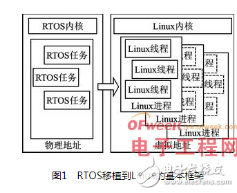


3. Led Color:White,Red,Green,Blue,Yellow and so on
4. Frenquency:customized
6. Led Quantity:1pcs,2pcs,3pcs,4pcs,5pcs,etc
7. Long Lifespan
8. Battery:AA, AAA, AG13, AG10, AG3 and so on environmental
9. PCB:Customized Size (OEM or ODM) or our existed standard size
11. Export to: USA, UK,Canada,Germany,
Turkey,Russia,Poland,Switzerland,Netherland ,Frence Hungary
,Australia,New Zealand, Brazil, Columbia,Argentina,Thainland,Singapore ,
Malaysia and so on
introduction