Medtronic's test engineering team must develop automated HV electric shock test solutions, and a total of 12 test modules can individually test 1 to 4 different products to reduce overall test time. With LabVIEW FPGA and NI Intelligent DAQ hardware, the team dramatically increased module communication speeds from 20 KHz (parallel communication åŸ ) to 1.7 MHz (FPGA), reducing overall test time. The previous manual system performs 12 modules synchronously through parallel communication. Only one HV electric shock device can be tested, and it takes 135 minutes to test 12 sets of instruments. The new automation system can perform 12 modules asynchronously via FPGA digital I/O communication and test up to 4 different types of 12 devices in 48 minutes. The Reentrant test sequencer and the test program can control each test module independently, so each group of test jobs can be guided by the Handling system. The host computer performing the test integrates the automation device operating system with the HV electric shock test system. Test automation The Test execuTIve system is the primary controller that provides the user interface, the load and unloading of the leading test modules, and allows the Test Manager to perform HV electric shock tests against the actual device or the device loaded on the test module. The Test Manager will determine the product under test and send the information to Test execuTIve, allowing the operator to select the product to be tested. The operator loads the product and starts testing according to each system setting, and the test processor then loads the DUT into the test module. Once the DUT is loaded, testing begins in a specific module. Test execuTIve and the test processor will continue to load the remaining DUTs during the test, and the Test Manager will test each set of DUTs until they are completed. The Test Manager can dynamically call up to 12 sets of Reentry Code Test Sequencers and then dynamically call the Reentrant Code Independent Test Program. Test manager will start the test program (Test execuTIve) according to the test executable file. The system manages all test modules and DUTs managed in the LabVIEW graphical programming environment. Each test module has a static set of attributes, where the values ​​will vary depending on the product type, test phase, hardware settings, and other processing attributes. When the current DUT test is finished, the test system will close the test queue in memory. The Test Manager will monitor the test status and notify the Test executive of the pass/fail status when the DUT completes the test. The test executive will then let the tester unload the DUT and place it in the Output tray. Then another set of DUTs will be loaded into the test module for the next test cycle. Each of the 12 test modules independently performs DUT loading, testing, and unloading cycles. The automated tester will load the load/unload job requirements into the queue. A total of two sets of NI PXI-7811R modules communicate with the test module and DUT via serial communication (SPI) and JTAG. Both NI PXI-7811R modules execute the same LabVIEW FPGA program, but have different synchronization mechanisms (Semaphore) and NI-VISA sources to control the module. The Test sequencer will dynamically call the Test Case from the test program to control the DUT test job. Since the memory must accommodate a test program with up to 12 sets of reentry codes or separate backups of the Test sequencer, some system performance must be sacrificed to include all subVI or subfunction reentry codes. Only these subVIs can form system bottlenecks or contain global functionality that can generate reentrant codes. This solution reduces the overall system memory usage to improve performance. All Test sequencers use the same FPGA as the test program, so the system uses a Semaphore or a Token to control each PXI-7811R module. All VIs must access the FPGA program to initialize the synchronization mechanism. Each FPGA system has an independent synchronization mechanism that allows one of the groups A (1 ~ 6) to access the first FPGA system; and one of the groups B (7 ~ 12) is almost synchronously accessed. The second FPGA system. The interaction of each set of FPGAs is extremely short – about a few milliseconds (Millisecond); therefore, this method is suitable for distributing FPGA source programs to support 12 groups of peers. Each test program for each module has approximately 600 FPGA interactions. FPGAs can execute 12 modules asynchronously at high speed to handle all traffic that the system can load. The test execution system is the main controller, which provides the user interface, the load and unloading degree of the leading test module, and allows the test manager to perform the HV electric shock test for the actual device or the device loaded on the test module. High Voltage Main Power Transformer
The main transformer, which is the main step-down transformer used for power transmission and transformation in a unit or substation, is also the core part of the substation.
High Voltage Power Transformer,The main transformer,main transformer Henan New Electric Power Co.,Ltd. , https://www.newelectricpower.com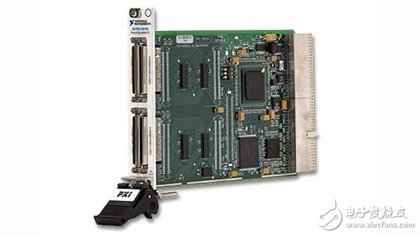
The AeroSpec test automation operating system will be responsible for removing the device under test (DUT) from the four input trays; reading the DUT serial number through the optical self-identification (OCR) function; loading or unloading the DUT with 12 test modules First, according to the test results, the DUT is placed in one of the 12 sets of output trays. Four different products can be set in 4 sets of input trays, each of which can hold 20 sets of units. 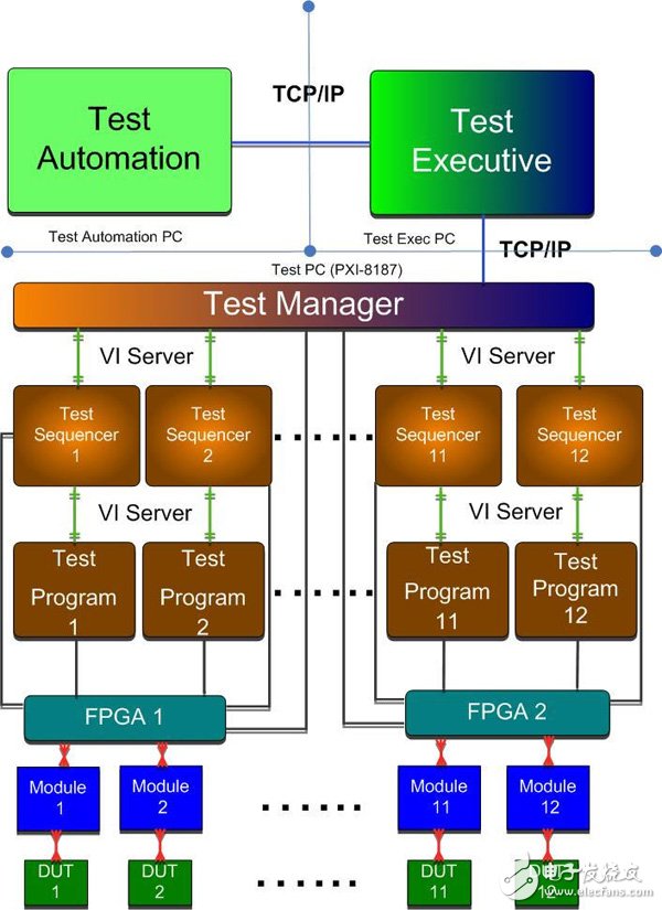
The main transformer is composed of the following aspects:
1. Body: The body directly converts electromagnetic energy, which is composed of iron core, coil, lead wire, insulation, etc.
2. Oil tank and cover: mainly composed of box, cover, bottom and accessories (such as 50 valve, oil sample valve, oil drain plug, grounding bolt, etc.).
3. Protection device: mainly composed of oil conservator, oil meter, oil purifier, gas relay, Moisture Absorber, thermometer, Pressure Relief Valve, etc.
4. Cooling mode: oil immersed self cooling, oil immersed air cooling, strong oil water cooling, strong oil air cooling.
5. Outgoing line bushing: It is composed of 25/300 cable bushing and BF-6/2000, BF-1/1000, BF - l/600 and BF-1/300 bushings.
6. 25 # or 45 # transformer oil is used as transformer oil to increase insulation strength and cool down the transformer;