Overview: 1 Introduction 2 Basic SVPWM Principle of 3-Phase 3-Level Inverter Figure 1 shows the hardware topology of a mid-point clamp (NPC) 3-phase 3-level inverter. Jiangmen Hongli Energy Co.ltd , https://www.honglienergy.com
Space Vector Pulse Width Modulation (SVPWM) is widely used in 3-phase inverter control systems. The most efficient way to implement an SVPWM MCU is center-aligned PWM because the PWM module in the MCU easily produces center-aligned PWM. This article will discuss the SVPWM implementation and introduce an easy way to implement center-aligned SVPWM, which is suitable for on-chip PWM modules.
SVPWM is widely used in 3-phase inverter control systems because it has higher DC-side voltage utilization efficiency than sinusoidal pulse width modulation (SPWM). Although SVPWM has many advantages, it is difficult to implement. The most difficult factor is calculating the duty cycle of each power switch and determining the vector sector and pulse sequence for each switching cycle. Many articles have introduced the duty cycle calculation method for 3-phase 2-level inverters, and we can use many methods to calculate the vector sequence (for example, the center alignment method, which can be easily implemented in the MCU platform).
In order to improve the system efficiency of 3-phase inverters, 3-stage or multi-level inverters are becoming more and more popular. Compared to the 2-level inverter, the 3-level inverter has more power switches (up to 12); this means that the 3-level inverter has more vector sectors than the 2-level inverter. . Therefore, the duty cycle calculation and vector calculation of the 3-level inverter SVPWM are more complicated than the 2-level inverter.
This paper [1] introduces a simple method of calculating vector sectors. The calculation process has only 2 steps in total, and the first step divides the entire vector into 6 main sectors. This step is very similar to the sector calculation method for a 2-level inverter. In the second step, the reference sector is relocated to one of the six sectors, and then the main sector is divided into six sub-sectors. This calculation method can be used for a 2-level inverter to determine the effective vector and calculate its dwell time. However, we have not discussed the vector sequence for each switching cycle, and the duty cycle calculation method is difficult to implement in MCU applications. This paper [2] uses the same method for calculating vectors. The repositioned zero vector is used as the zero vector of the 2-level inverter, and the resulting vector sequence is the same as the 2-level inverter. In the implementation process, the MCU is used to generate a sequence signal and peripheral logic is used for the implemented PWM generation of each power switch. We have not introduced a method that does not have peripheral logic and is suitable for MCU implementation.
The most efficient way to implement an SVPWM MCU is center-aligned PWM because the MCU's PWM module easily produces center-aligned PWM. This article will discuss the SVPWM implementation based on the methods described in [1] and [2], and introduce a simple method for implementing center-aligned SVPWM, which is suitable for on-chip PWM modules. 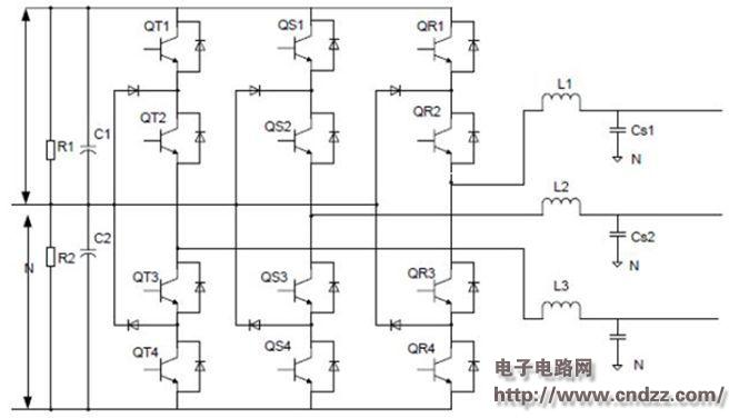
(Please read the PDF for details)