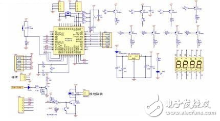
The temperature control switch mainly uses a dish-shaped bimetal as a temperature sensing component. The working principle of the temperature control switch is: when the temperature rises, the dish will produce corresponding deformation, and when the temperature reaches the dish shape At the value of the deformation, the jump of the disc depends on the mechanical transmission of the other device, causing the contact to act quickly to turn the current on or off. Operating temperature range: 30 ° C -300 ° C. The temperature control switch is prone to three problems: First, when the temperature of the bimetal disc of the temperature control switch itself is too high, the steam of the electric kettle cannot make the bimetal disc reach the temperature of the jump, resulting in the temperature control switch. Unable to cut off the current, the water of the electric kettle has been boiling and can not stop causing danger; secondly, the bimetal is a mechanically processed accessory. The jump and reset have mechanical life, and the material problem or processing problem has a direct impact on the life of the bimetal. Assume that a kettle is used normally for 5 times a day, and nearly 2,000 times a year. To ensure that the kettle is used for more than 5 years, the temperature control switch or bimetal must be used for more than 10,000 times. The small spring of the switch is the same as the bimetal. It is also a mechanically processed accessory. Its life also directly affects the life of the temperature control switch and even the electric kettle. Therefore, the research and design of the temperature control switch life tester is essentially a life tester for testing bimetal and jump small springs. In the actual production test, the method of sampling is selected for testing. Circuit board part: This part uses the MCU as the core of intelligent control. The temperature of the test kettle is collected by the DS18B20 temperature sensor, transmitted to the MCU for processing, and displayed in the LED or digital tube. The test encounters a fault or the test is completed. A corresponding sound and light indication is issued. The circuit schematic is shown in Figure 4. Figure 4 Circuit diagram of the temperature control switch tester 24V Ac Dc Adapter,Ac/Dc Power Adapter 24V,Dc Adapter 24V,24Volt 500Ma Power Adapter ShenZhen Yinghuiyuan Electronics Co.,Ltd , https://www.yhypoweradapter.com