A separate slip ring is a device that allows two or more rotating electrical shafts to be connected without having to pass the electricity through the shafts' bearings. This is often used in situations where there is a need to power something externally while the shaft is still turning. For example, a machine might have a drive shaft that powers it while also having a separate output shaft that needs to turn at a different speed. By using a separate slip ring, these two shafts can be powered without any interference.
Slip Ring Shaf is a key component of a slip ring. It is the shaft on which the rotary electrical contacts are mounted. The shafts must be strong enough to support the weight of the contacts and must be able to turn freely. There are many factors to consider when selecting a shaft material, including strength, corrosion resistance, and operating temperature.
Oubaibo is a professional separate slip ring manufacturer located in China. They offer a wide range of slip ring shaft made from different materials, including carbon steel, stainless steel, and brass. Their products are made to meet the highest quality standards and are backed by a 100% satisfaction guarantee.
Separate Slip Ring,Slip Ring Shaft,Slip Ring 4 Wire,Slip Ring For Motor Dongguan Oubaibo Technology Co., Ltd. , https://www.sliprobo.com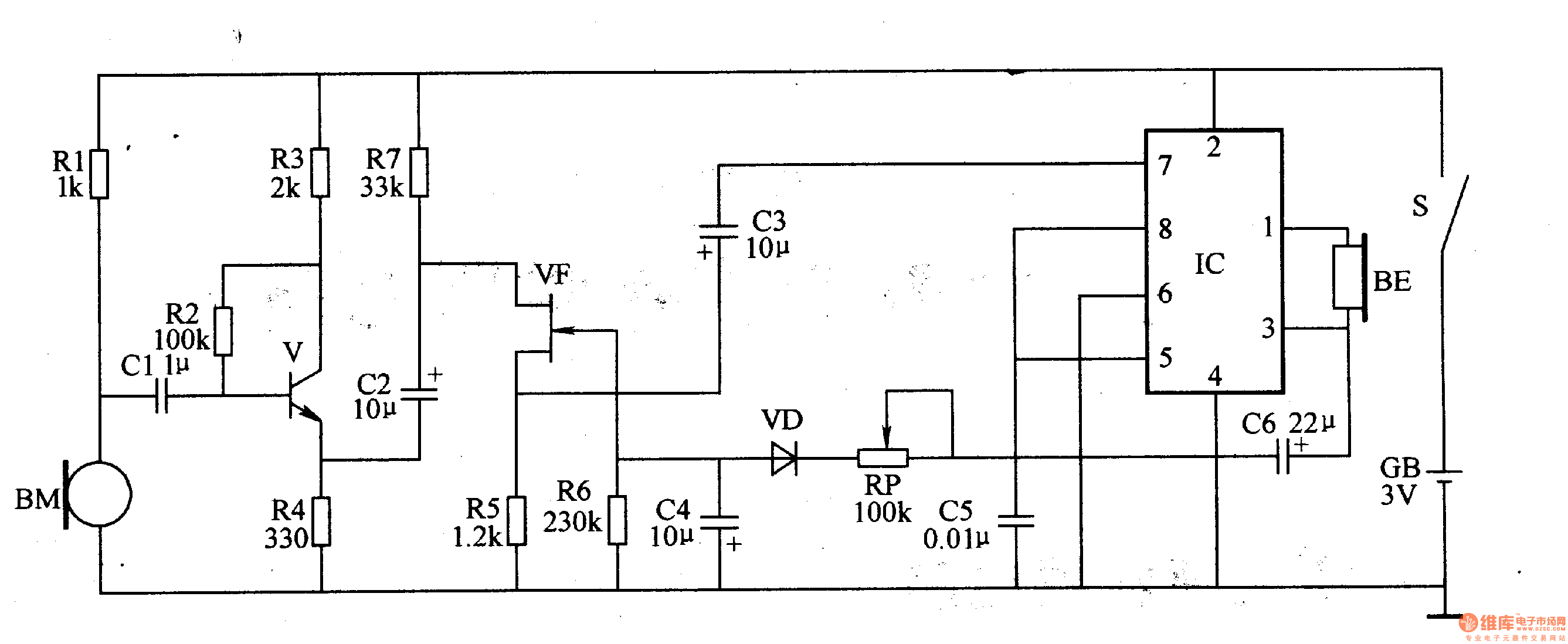
The input amplifying circuit is composed of a microphone BM, resistors R1-R4, a capacitor C1, and a transistor V.
The volume control circuit is composed of a field effect transistor VF, a volume potentiometer RP, resistors R5-R7, capacitors C2, C3, C5 and a diode VD.
The audio power amplifying circuit is composed of an audio power amplifier integrated circuit IC, capacitors C4, C6 and a headphone BE.
After the power switch S is turned on, the whole machine is energized. The BM receives various sound signals and converts them into electrical signals. The electrical signals are amplified by V and VF, and then added to the 7th pin of the IC through C6. After further power amplification by the IC, the headphone BE is sounded.
A part of the IC output signal is rectified and filtered by C5, RP, VD, and C3, and a negative voltage is applied to the gate of the VF, and the input and output signal voltages of the IC are adjusted by controlling the impedance between the drain and the source of the VF. Achieve automatic control of the volume.
Adjusting the resistance of the RP can change the level of the negative voltage of the VF gate, thereby changing the volume of the headphone.
Component selection
Rl-R6 uses 1/8W metal film resistor or carbon film resistor.
The RP uses a small band switch (power switch S) potentiometer.
Both Cl and C4 use monolithic capacitors; C2, C3, C5 and C6 are all ultra-small aluminum electrolytic capacitors with a withstand voltage of 6.3V.
VD selects 2AP9 type é”— ordinary diode or 2AK series é”— switching diode.
V selects S9014 or 3DG6 type silicon NPN transistor.
VF uses a 3DJ6 junction field effect transistor.
The IC uses TDA2822 or D2822 type audio power amplifier integrated circuit.
BE uses 8Ω high-fidelity headphones.
The BM uses a high sensitivity electret microphone.