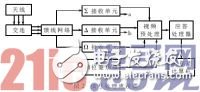
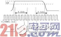
A single-pulse secondary radar response processor implemented with EPLD. Its main functions include: response frame pulse detection, response information decoding, assembly of response information into aircraft synchronization response groups to form target reports, and discarding asynchronous false responses. The secondary radar and the primary radar are basically developed in parallel. Compared with primary radar, the secondary radar has the characteristics of strong echo, no target flicker effect, and the interrogation wavelength and response wavelength are different, thus eliminating the interference of ground clutter and meteorological clutter. The single-pulse technique is applied to the secondary radar, which can be conveniently based on multiple beam-to-target measurements, thereby effectively increasing data redundancy and improving the accuracy of angle measurement. For the response processing, the application of the single-pulse technique greatly improves the decoding ability of the response code in the case of aliasing or interleaving, so that the single-pulse secondary radar achieves a qualitative leap compared with the conventional secondary radar. The fundamental difference between secondary radar and primary radar is that it works differently. The primary radar relies on the target to work on the reflection mechanism of the electromagnetic waves emitted by the radar. It can actively find the target and locate the target. The secondary radar works in the question and answer mode in cooperation with the ground station and the target transponder. The current air traffic secondary radar has seven inquiry modes, which are called 1, 2, 3/A, B, C, D, and S modes. The various interrogation modes are determined based on the pitch of the interrogation pulses P1 and P3 (except for the S mode). The response code sent by the onboard transponder consists of 16 information code bits. The codes of these code bits are F1, C1, A1, C2, A2, C4, A4, X, B1, D1, B2, D2, B4, D4. , F2 and SPI. Each code bit has two states, one with or without pulses. It is "1" when there is a pulse and "0" when there is no pulse. The pulse leading edge interval at the 0.5 level of F1 and F2 is 20.3 ± 0.1 μs, which is called the frame pulse, which is the flag pulse of the secondary radar response signal, and is always in the "1" state. The X bit is the standby state and is always "0". The 12 information code bits between the two frame pulses (F1 and F2) can be programmed into 4 096 independent response codes. The SPI is a special positioning identification code. When two aircraft are close to each other or the answer code is the same, the dispatcher can request one of the aircraft to add another SPI pulse based on the 12 code bits that have been answered for accurate identification. The composition of the secondary radar response signal is shown in Figure 1. The basic flow of single-pulse secondary radar response signal processing is shown in Figure 2. In the video pre-processor, the ∑ and Δ video signals of the sum and the differential branches are digitized by the A/D converter, and then become two sets of 8-bit digital signals transmitted to the response processor; Δ The signal of the receiving unit is generated by the phase discriminator to generate an axial indication signal BI (2 bits) indicating that the target is on the left or right side of the beam center, and sent to the response processor; ∑ and Ω are compared with the video amplitude to generate a response response. The sidelobe response is also the RSLS (1 bit) of the main lobe response; the received signal is subjected to 6dB detection, inverse narrow processing, and two layers to generate PSV (processed and video, 1 bit). The video preprocessor generates the above signals and inputs them to the response processor for frame detection, difference ratio calculation, code assembly, etc., and finally forms a response report output to the point/track processing computer. The composition of the response processor system is shown in Figure 3. The EPLD of LatTIce was selected as the main processing chip (ispLSI1032E) in the response processor. The chip has 64 I / O terminals, 8 designated inputs, 6 000 logic gates, 192 registers, maximum delay ≤ 12 ns, through a simple 5-wire interface, you can use the PC to daisy chain structure on the circuit board Up to 8 chips are programmed. PC104 is an embedded computer, its CPU is a compatible 64-bit sixth-generation processor, running at speeds up to 300MHz, its graphics processor can support a variety of LCD and TFT display, while supporting PS/2 keyboard, PS/2 Mouse, two serial interfaces, a parallel interface, USB interface, sound card function. The working principle of the answering processor: 1-bit PSV, 8-bit and video, 8-bit difference video, 2-bit axial indication and 1-bit receiving sidelobe suppression signal, after passing the input buffer and synchronizing with the system clock signal, the PSV The signal enters the edge generation circuit, and the generated leading edge is delayed by a frame time (20.3μs) and the target frame is given with the undelayed leading edge signal, and the assembler in the idle state of the four decoders is started to start the decoding work, and the decoding is generated. The required timing pulse sequence. Simultaneously, the video, the difference video, the axial indication, and the sidelobe suppression signal are sent to the video sampling circuit, and the SVA value is generated by the SVA (and video amplitude) and DVA (difference video amplitude) and the difference ratio calculation circuit generated by the video sampling, SVA. , DVA, SDR send digital register for delay, delayed and undelayed SVA, SDR, axial indication, receiving sidelobe suppression and target leading edge signal are sent to the code assembler, under the action of timing pulse, the target response information is performed. Decode, remove phantom responses, resolve sidelobe responses, and military emergency responses. After further correlation, confirmation and correction, the target SVA and SDR code, integrated code confidence information and some flag information are sent to the code assembly bus, and in the case of output control, the first in first out (FIFO), PC is sequentially written. The GPS time information and the target report in the FIFO are sequentially read. 3.1 Sidelobe suppression and edge extraction Close-range aircraft can be detected by the side lobes of the antenna, but without special side-lobe suppression measures, the ground receiving device receives response information from the side lobes, thereby exaggerating the number of aircraft. P2 is transmitted as the sidelobe suppression pulse by the Ω channel. In the main lobe beam of the antenna, the amplitude of P1 and P3 will be higher than P2, and in the side lob of the antenna, P2 will be higher than P1 and P3, and the airborne transponder is based on The magnitude relationship between P1, P3 and P2 determines whether a response is made and does not respond to interrogations within the side lobes. The PSV signal of the single-pulse secondary radar is a 0 or 1 level outputted by the response signal in the receiver and the channel (∑) after being binarized by a specific threshold level. The extraction of the front and rear edges allows the PSV signal to be input to two registers, which is implemented by an AND circuit. The realization circuit is shown in Figure 4. ALE and ATE are the same leading and trailing edges as the clock pulse width (0.1208μs). When the width of the PSV signal is greater than the width of a response code, it is considered that the aliasing of two or more pulses is received, thus generating a pseudo leading edge (PLE). The generation time of the PLE is four clock cycles from the ATE (because a standard pulse width is four clock cycles). If the pulse width of the PSV is longer, it can be considered that there are more overlaps of the response pulses, one The extra leading edge (XLE) is generated between ALE and PLE and is only used to help determine the correctness of the results in later processing. The relationship between the leading edge and the PSV is shown in Figure 5. 3.2 Video Sampling Video samples are divided into ALE samples and PLE samples. The ALE sample uses the 4&TImes;4 register array so that more than one sample value can be stored. To ensure the setup and hold time of the register array, the ALE pulse is delayed by a delay of 40 μs and the write pulse is limited to 30 μs. The write address of the register array is generated by a 4-bit counter, and each sample pulse counter is incremented by one. The difference between PLE sampling and the ALE sampling circuit is that it only needs to store one PLE sample value. The sampling clock of this system is 8.276MHz. 3.3 SDR calculation Since the logarithmic operation is used in the SDR module, it is only necessary to invert the difference signal and connect it to the input of the adder when performing the operation of the ratio of the amplitude to the difference amplitude. In addition to the sum signal outside the center of the beam being less than the difference signal, Δ-∑ has a negative peak at the center of the beam, so the center of the beam is at the maximum of the negative peak. According to other values ​​of Δ-∑ and with reference to the negative peak, it can be converted into an angle deviating from the center of the beam. 3.4 Frame Detection and Response Decoding Normally, the interval between the two frame pulses is 20.3 ± 0.1 μs, so a frame considers there are 167, 168 or 169 clock cycles between the two leading edges. The detection of the frame pulse of the system is based on the coincidence of the leading edge and the non-delay of the comparison delay, as shown in Fig. 6. The leading edge of the delay corresponds to the frame pulse F1, the leading edge of the non-delay corresponds to the pulse F2, and the delay of F1 with respect to F2 is 20.3 μs. Since F2 has a range of three clock pulses relative to F1, the alignment of F2 with F1's leading edge delay of 167, 168, or 169 clock cycles is considered a correct frame. Frame detection will be banned in the following three cases: (1) Both F1 and F2 are response signals from side lobes; (2) the interval between two adjacent frames is less than 3 clock cycles; (3) The head response of the S mode is detected, and the frame detection is disabled for 120 μs because an S mode response lasts for 120 μs. The response information is interwoven to create a phantom frame, as shown in FIG. If only the frame time interval is 20.3 μs, only four frame pulse pairs can be detected. The frame detector cannot distinguish between the “false†frame and the real frame pulse pair from the aircraft. The remedy is to process only two responses at the same time. When the first response is detected, then the response detected in 21μs is a temporary response. If an overlapping response is found, the temporary response is cancelled. This process is repeated until the last response is detected. This response is retained. . Because the first detected frame is definitely a true response, no earlier pulse produces an error frame. Again, the last frame is definitely a true response, no later pulses can produce an error frame, and the frames detected in the middle are suspicious, assuming they are incorrect. When a correct frame is detected, the next task is to detect the contents of the response code. First, the decoding process is based on a time interval of 1.45 μs between each response code, and the time interval between SPI and F2 is 4.35 μs, so that a presence of a response pulse is detected at a position where each response code of the frame pulse may occur. Considering that there is a certain allowable error between the time interval between each response code and the frame pulse, the position of the correct response code is considered to be the advance response or the delay one clock cycle at the position where the response code corresponding to the frame pulse appears. Comparing the value at the position where the response code may appear with respect to the frame pulse with the frame pulse (non-sidelobe pulse), the response code is 1 or 0, and there are several cases: (1) High confidence 0: The presence of the acknowledge pulse is not detected where the response code appears. If only the amplitude is measured, only the low amplitude value appears. (2) High confidence 1: The response code in the main beam appears where the response code appears. The amplitude is related to its corresponding reference pulse and is not related to the reference pulses of other responses. (3) Low confidence 0: If the response pulse is marked as a sidelobe response pulse or if the response pulse is not correlated with the corresponding reference pulse, it is related to the reference pulse of the other response. (4) Low Confidence 1: The main beam response code is present but is not related to the reference pulse or to the reference pulse of the other response, or both to the corresponding response frame and to the other frame. 3.5 code assembly The code assembly consists of two parts: the SVA code assembler and the SDR code assembler. The function of the SVA code assembler is determined according to the SVA average value, and the corresponding confidence code bit is generated; the function of the SDR code assembler is to check the content of the response pulse when detecting a frame pair F1 and F2. For each code bit, a confidence determination is made based on the SDR average, a corresponding confidence code bit is generated, and the code and confidence bits are combined with the corresponding bits from the SVA assembler. Because there are up to four responses processed simultaneously, there are four identical sets of SVA code assemblers and SDR code assemblers. The main working principle is: in order to obtain the average value of SVA, it is necessary to establish a reference value of SVA at the beginning of a response. In general, F1 is used as a reference value. If F1 is a sidelobe response or a reflection response, F2 is used as a reference value. When the response code is compared with the reference value and a high confidence code is obtained, the generated SVA value is considered to be a response code. The working process of SDR is similar to SVA. Combine the SVA code/confidence with the corresponding SDR code/confidence, the serial output code and the confidence code are output to the FIFO through serial-to-parallel conversion, and the computer (PC104) reads the contents of the FIFO and sends it to the point/voyage. Trace computer processing, showing information about the aircraft. Secondary radar plays a very important role in civil aviation systems and military enemy identification systems. As the density of aircraft increases, higher requirements are placed on the performance of secondary radars. By using the above-mentioned response processor, the single-pulse secondary radar achieves the processing capability of ≥400 batch/antenna rotation, and at the same time, the processing precision is improved, the volume of the system is reduced, and the flexibility is increased.
With the development of the times, the consumption level of people is gradually increasing. At the same time, people's entertainment methods are beginning to diversify, especially for modern young people. As a result, different kinds of electronic products are starting to be in people's lives, and the booming Electronic Cigarette industry reflects this.
Described including the upper shell, the upper shell at the top of the smoke outlet, as described in the bottom of the upper shell with airway, described with the smoke outlet in the airway and also to match the upper shell, the lower part of the shell described the airway in the direction of the lower shell extension, as described in the lower shell near one end of the upper shell is equipped with oil mouth, described the lower shell with batteries, described at the bottom of the bottom shell has come in The air port is provided with an oil storage bin in the lower shell, and the air passage passes through the oil storage bin and is provided with a heating atomization bin at one end away from the smoke outlet. The utility model has beneficial effects: it can meet the smoking habit of different users, avoid the premature end of the use experience caused by excessive consumption of smoke oil, and indirectly prolong the service time and life of the product.
Refillable E-Cig Oem,Refillable Vape Pod,Refillable Vape Pen Oem,Refillable Mod Oem Shenzhen MASON VAP Technology Co., Ltd. , https://www.e-cigarettefactory.com