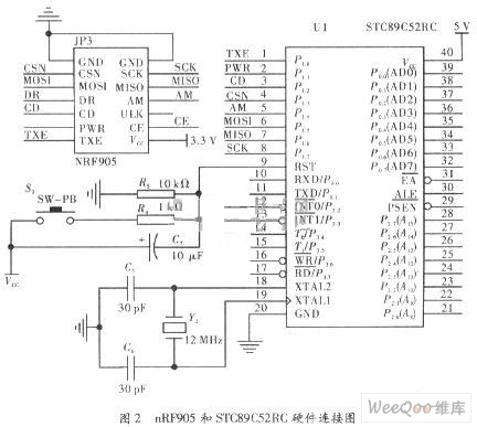
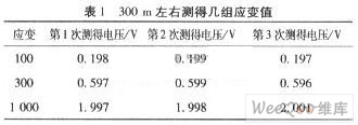
Design of wireless data transmission system based on SPI bus Abstract: Through the wireless data communication equipment based on SPI bus, the wireless data transceiver chip NRF905 and the 51 single-chip STC89C52RC are used for the design. The wireless data transmission system block diagram and software and hardware design are given. The SPI bus structure, NRF905 wireless radio frequency chip and a method of simulating SPI interface based on single-chip microcomputer are introduced, so that it becomes a reality that the single-chip microcomputer without SPI interface can be expanded to a peripheral chip with SPI interface. Discussed how to realize the configuration of NRF905 through SPI and use C language to realize this function. Finally, the data to be sent is sent, and the receiving end displays the data to realize the wireless data transmission system. Experiments show that the device has accurate and effective data transmission function. Short-range, convenient and cheap wireless communication technology is becoming the focus of attention, making people's demand for it higher and higher. For example, wireless data collection, wireless device management and monitoring, wireless meter reading, and wireless communication under the mine are all typical applications. 1 Overall system structure In this paper, 51 single chip microcomputer and wireless data transceiver chip NRF905 are used to form a wireless data transmission system, and the hardware and software design schemes are given. The data transmission process is: after the analog signal input from the sensor is collected by AD, the data is input to the single chip, and then the single chip sends the data to the NRF905 through the SPI interface, and the NRF905 automatically adds the preamble and CRC code to the data. Packet sending. When the NRF905 at the receiving end receives valid data, DR is set high; after the microcontroller detects that DR is high, it resets the TRX_CE pin to make the NRF905 enter idle mode, reads the received data from the NRF905 through the SPI interface, and then through the serial port The host computer displays. This article mainly introduces the two parts of 51 single-chip microcomputer software simulation SPI and wireless data transceiver. Figure 1 is a block diagram of the overall structure of the system. 2 SPI bus The SPI (Serial Peripheral Interface serial bus interface) bus system is a synchronous serial peripheral interface, which enables the MCU to communicate with various peripheral devices in a serial manner to exchange information. The interface generally uses 4 lines: serial clock line (SCK), master input slave output data line MISO, master output / slave input data line MOSI, and low-level slave selection line SS. It can be seen that the SPI bus only needs a few wires to communicate with various devices with the SPI bus hardware interface function, and the SPI bus interface is used to simplify the circuit design, saving many I / O lines for other functions and improving Design reliability. For some devices that do not have an SPI hardware interface, I / O port lines can be used to simulate SPI. Because the NRF905 radio frequency transceiver module is controlled by the MCU through the SPI interface, and the single-chip computer without the SPI interface is used, the SPI bus interface can only be simulated through the I / O port of the single-chip computer to realize the design of the wireless communication system. In this way, when the transmission speed requirement is not too high, using the I / O port to simulate the SPI bus can not only increase the types of application system interface devices, but also improve the performance of the system and save costs. 3 NRF905 wireless transceiver chip NRF905 is a monolithic radio frequency transceiver launched by Norway Nordic VLSI company. The operating voltage is 1.9 ~ 3.6 V. It works in the three ISM frequency bands of 433/868 / 915MHz, the channel switching time is <650μs, and the maximum data rate is 100kbit / s. NRF905 is composed of frequency synthesizer, receiver demodulator, power amplifier, crystal oscillator and GFSK modulator. The preamble and CR check code are automatically generated and can be easily programmed and configured through the SPI interface. Peripheral device connection is simple, no external SAw filter is needed. NRF905 has two working modes and two energy-saving modes. The two working modes are ShockBurst TM sending mode and ShockBurst RM receiving mode, and the two energy-saving modes are power-down and SPI programming mode, Standby and SPI programming mode. The working mode of NRF905 is determined by the settings of the three pins TRX_CE, TX_EN, PWR_UP. 4 NRF905 and STC89C52RC hardware connection circuit NRF905 has a standard SPI hardware interface. For STC89C52RC single-chip microcomputer without SPI serial bus interface, software can be used to simulate the operation of SPI. The corresponding connection method of the one-chip computer and NRF905 is: P1.6 connects MISO, P1.5 connects MOSI, Pl.7 connects SCIOCK, P1.3 connects CSN. The P1.5 analog data output terminal MOSI of the single chip microcomputer is used; the Pl.6 analog data input terminal MISO P1.7 simulates the output terminal of SCK; P1.3 simulates the slave selection terminal CSN, and the I / O port is cleared by the program The NRF905 communicating with it is a slave. When using SPI for data transmission, the 89C52 configuration NRF905 commands and data are moved in through the MOSI pin on each falling edge of SCK, and the data to be transferred to 89C52 is moved out from the MISO pin on each rising edge of SCK. Therefore, the initial state of the serial clock output port P1.7 is set to low level, and the slave is strobe, that is, after P1.3 = 0 low level, then P1.1 is set to high level. In this way, while the 89C52 outputs a 1-bit SCK clock, it will shift the data in the NRF905 serially to the left, thereby outputting 1-bit data to the P1.6 port of the 89C52. Output 1-bit data to NRF905, and the analog 1-bit data transmission is ended. Follow the above steps 8 times to complete the operation of transmitting 1 bit through the SPI bus. NRF905 has 5 internal registers, namely status register, RF configuration register, send address register, send data register and receive data register. These 5 registers are all configured through the SPI interface simulated by 89C52 software. In addition to the configuration of the register, 89C52 also has to switch the control of the working mode of NRF905. 5 Power circuit design This system uses two power supplies, the single-chip microcomputer STC89C52RC uses 5 V power supply, NRF905 uses 3.3 V power supply for power supply, and then STC89C52RC and NRF905 share the ground, otherwise it will appear unable to transmit data. Among them the conversion chip uses AMSlll7-5. 0 to 5 V chip and AMSl117-3. 3 to 3.3 V chip circuit diagram, as shown in Figure 3. The power circuit uses the 9 V DC output from the 220 V AC adapter, filters it into AMSlll7-5. 0 through C1, and then connects a 100μF capacitor at the output to perform filter decoupling, thereby obtaining a 5 V DC voltage for use by the microcontroller; then 5 V voltage is connected to the next level AMSlll7-3. 3 power conversion chip, output 3.3 V for NRF905 use. 6 C language implementation of software design For the sending end, first initialize the I / O port and SPI interface, then configure the NRF905 registers and initialize each interface. After initialization, process the collected data, set NRF905 as the sending mode, call the sending code, and delay for a period of time Time, wait for the data to be sent; similarly, the same initialization is performed at the receiving end, the difference is that after the initialization is completed, the NRF905 module is set to the receiving mode, and then the receiving program is called. Finally, display on the host computer through the serial port. 7 Experimental analysis This paper designs and debugs its hardware and software, and builds a SPI wireless communication system platform. The experiment proves that through this system, the stress of the board and shell is tested wirelessly. At the NRF905 transmitting module end, the board and shell are deformed, and then the strain gauge sensor is used to measure the voltage value of the deformation, and the analog signal is AD collected before data transmission. And transmit the collected data through the wireless transmitting module; at the same time, first place a receiving module at a distance of 50 m from the transmitting module to receive the transmitted data and display it. Then the distance increases by 50 m after each experiment. To judge their longest transmission distance under the condition of ensuring stable signal transmission. The best results are measured between buildings within 350 m of each other, and the data transmission is stable. When it exceeds 350 m, the data display appears and disappears. Table 1 shows several sets of strain values ​​actually measured around 300 m. 8 Conclusion In this paper, the implementation method of data transmission using SPI bus interface is introduced. A wireless data transmission system is designed using NRF905 RF transceiver chip and STC89C52RC single chip microcomputer. After completing the hardware circuit and system software debugging, a wireless data transmission and reception experiment is carried out. The experiment process is to use the strain gauge sensor to measure the analog signal of the board shape, which is collected by AD to generate the data to be sent, and then to transmit, receive and display it. Experimental results show that the wireless transmission system works stably and communicates with buildings 350 meters apart. The received and transmitted data are identical. This shows that the system can effectively transmit data, and has the advantages of high speed and strong anti-interference ability. Battery holders are key components in many types of portable and anchored electrical items - and you`ll find just as many varieties, brands, sizes and types of battery holder available across global markets as there are different sorts of battery.
In this guide, we`ll look more closely at some of the various mounting styles a battery holder might come fitted with, as well as the many different cell sizes they`re designed to work with.
What is a battery holder?
Holders and mounts for different battery sizes
Battery holder mounts
Panel Mount Battery Holders
Surface Mount Battery Holders
Battery Holders ATKCONN ELECTRONICS CO., LTD , https://www.atkconn.com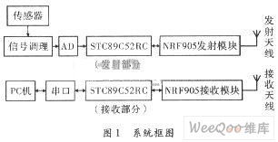

Battery Holders & Mounts
A battery holder is most commonly sold as an integral or removable compartment or cavity, designed to be inserted into - or attached onto - a suitable item of cell-powered equipment.
The primary function of a battery holder is to keep cells fixed in place safely and securely while conveying power from the batteries to the device in question. External connections on battery holders are most often made by contacts either with pins, surface mount feet, soldered lugs or via a set of wire leads.
Battery holders are often designed to be incorporated within the body of an electrical item, but they`re also frequently sold as external compartments or attachments. Either way, some of the most important factors to consider when choosing an appropriate battery holder for a given application will be:
Battery size
Compatible cell types
Contact/terminal style
Battery mounting and insertion method
Unit size and shape
Battery holder cover and housing design
Build quality and manufacturer reputation
Many different battery holder sizes and mounting types are available from manufacturers and suppliers all over the world. Most will be made to work with a particular sort of cell - or sometimes with a range of multiple battery sizes - and to be affixed to the electrical item in question in a specific way.
Bear in mind that, in addition to sorting through the wide variety of battery holder sizes and capacities on the market, you`ll also need to be mindful of the many options available in terms of actual battery chemistry.
While the vast majority of holders and mounts will be able to accommodate most battery chemistry types, each will have its own unique set of pros and cons in terms of performance, power drain, longevity, cost and environmental impact.
Common battery types sold by many suppliers might include:
Alkaline batteries
Lithium batteries
Rechargeable batteries (including li-ion)
Nickel cadmium batteries
Nickel metal hydride batteries
NiZN batteries
The above range of cell types is often available across a broad range of popular battery sizes and shapes, including both AA and AAA versions. Most, but not all, will be interchangeable in a wide range of devices, holders and mounts. However, it`s seldom advisable to combine mixed battery chemistries in a single electronic device.
Doing so can often impede device performance, as the item drawing power will only ever perform to the capabilities of the weakest battery in the holder. Of even greater concern is the fact that more powerful batteries can sometimes force weaker ones to work harder than they`re intended to, causing them to drain to very low voltage levels and possibly leading to potential leaking or rupture.
As such, it`s always wise to ensure you know which cell types you`re likely to be using in advance of making a purchase, as well as the correct sizing you`ll require.
AA Battery Holders & Mounts
An AA size battery holder is one of the more common types of battery storage compartments you`ll see on sale from UK suppliers. AA size (`double-A`), is what most people would typically think of as a `standard` battery, and remains extremely common in all kinds of portable electrical items and equipment.
AA battery pack holders can be manufactured to house any number of cells in theory, but in daily use it`s usually anywhere between 1-10 batteries, with 2-8 being by far the most popular options. AA single battery holders are also common.
Relatively few cell-powered tools or other pieces of electrical equipment will be designed to require more than 8 AA batteries for achieving sufficient power supply. Items that demand a higher power draw than this will usually be built around a larger cell type, for improved practicality and less frequent need for battery replacement or recharging.
AAA Battery Holders and Mounts
Battery holders for AAA cells, commonly referred to as `triple-A` are another very common configuration. AAA batteries are smaller and slimmer than AA versions, with around a third of the storage capacity.
Due to the increasing efficiency of many device types, AAA batteries are often found in more compact pieces of equipment that would typically have been expected to run off double-A cells in years gone by. Today, these will very often include low-drain portable or handheld electronic goods or tools, such as:
Remote controls
Mp3 players, handheld gaming systems and other portable entertainment devices
Digital cameras
Cordless mice or keyboards
Flashlights and other portable lighting units
Clocks and alarms
Kitchen gadgets
AAA battery holders are generally built to accommodate fewer individual cells than bigger units for housing AA and larger capacity batteries, as devices requiring more power will typically not run off triple-A cells.
An AAAA battery holder is a somewhat less common configuration, given that the much smaller than average AAAA (`quadruple-A` or `four-A`) cell standard drains considerably faster than AA or AAA equivalents.
C Battery Holders and Mounts
C size battery holders are designed around the fairly common C battery (sometimes known as an R14). This is a fairly wide diameter cylindrical cell, smaller than D batteries while being the same height - but significantly wider - than AA standard.
C cell batteries, holders and mounts are less widely used than either AA or D versions, particularly since power efficiency is continually improving across most cell-powered devices. However, they can still often be found on a range of medium-drain electronic items, including:
Heavier flashlights and smaller ambient lighting fixtures (e.g. table lamps)
Radios and portable speakers
Toys and games Musical instruments and amplifiers
D Battery Holders and Mounts
D batteries are among the larger types of `everyday use` cells you`ll commonly encounter around the home or workplace. D size batteries tend to be used for higher-drain devices that tend to be used for longer periods at a time, including:
High Power torches and flashlights
Safety systems
Geiger counters
Megaphones, larger musical instruments and more powerful audio devices or speakers
Motorised toys and portable gaming consoles
Products with inbuilt electric motors
Battery holders for D cells are most commonly sold in configurations designed to house either 2 or 4 individual batteries.
12V Battery Holders and Mounts
Battery holders for 12V cells are somewhat less widely available, chiefly because the 12V standard incorporates such a wide range of battery shapes and sizes, although 12V Battery Contacts themselves are more commonly sold as separate components (see Battery holder mounts, below).
The precise sort of 12V battery you might need for specific applications will dictate the appropriate form factor, which can be anything from a large heavy car battery type to one closely resembling a traditional AA cell.
With larger 12V batteries, in particular, it`s less common to need more than one at a time, and they`re generally built more intrinsically into the device or equipment being powered than other types of `snap in/out` batteries designed for frequent and quick replacement. This means that 12V battery holders and mounts aren`t as frequently sold by many UK suppliers as versions for other, more common cell types.
Battery holder mounts usually refer to the way the battery holder itself is slotted, secured or attached onto or into the main body of the item being powered. Note, however, that the term `battery mount` is also used to refer to the method by which individual cells are held in place within the overall holder unit.
Battery holder mounts and battery mounts are usually present as an integral part of a complete holder unit, but you can also buy battery mounts cheaply as swap-out or replacement parts. They can come in many different configurations and designs, with some of the more common types being:
Chassis mount
Panel mount
PCB mount
Slide-in mount (usually refers to the battery insertion method)
Snap-in mount (usually refers to the battery insertion method)
Strap & lead mount (a battery connector, rather than a holder per se)
Surface mount
Through-hole mount
Wire lead mount (refers to connection type)
In this section, we`ll look at some of the most widely used battery mount types in everyday use
Chassis Mount Battery Holders
A chassis mount battery holder denotes one intended to be affixed to a surface plate within the main body of the device being powered, and will usually remain in place while batteries are being swapped. A chassis mount holder is usually attached either via fixing holes in the back of the casing - i.e. a through-hole mount - or via tabs located around the sides of the battery holder.
Chassis mount battery holders can be either metal or plastic, open faced or enclosed (i.e. with or without a cover), and are commonly designed to accept a wide range of cell sizes including AA, AAA, C, D and 9V PP3
A panel mount battery holder is designed to be slotted into a pre-existing cavity in the side, top or back exterior panel of a device, and removed entirely as a single self-contained unit when it`s time to swap out the batteries. They`re often manufactured such that the cover of the battery holder will sit flush with the device`s panel once inserted
Panel mount battery holders are most commonly secured in place via one of two methods - either via a screw-in system for optimal stability or with a flange for easier removal and reinsertion.
PCB Mount Battery Holders
As the name implies, a PCB mount battery holder is intended for applications where the battery holder needs to be installed directly onto a printed circuit board
The most common design is for the PCB mount holder to include several small sharp pins around its perimeter - these are pushed directly through the surface of the PCB and then soldered on from the rear side
Holders for PCB mounted batteries can be made from metal or plastic. While they`re frequently built to accommodate single coin cells, such as you might find on a typical computer motherboard, they can also be configured to allow for multiple cells and other battery types, including cylindrical AAA, AA, C, or D cells
Slide In Mount Battery Holders
As noted above, a slide-in mount battery holder will generally refer to the way the individual cells are inserted into and removed from the battery holder as a whole.
Slide-in mounts are arguably the most common type of battery connection/terminal setup, requiring the user simply to `drop` the cells into place either lengthways or side-on, at which point they`re either held in place by opposing forces from the two terminals, or secured with a cover or cap
Slide-in battery mounts tend to be among the cheapest and most cost-effective choices to buy in the UK for quickly and simply inserting a cell into an appropriate holder. They work reliably well, and are most often seen in molded plastic or metal battery holders incorporating self-contained battery compartments.
Snap-In Mount Battery Holders
A snap-in mount battery holder (sometimes called snap-on, depending on the manufacturer or supplier) denotes a terminal/contact setup where the cell is held more securely in place.
This is usually achieved using tensioned metal clips, sometimes incorporating springs, through which the battery needs to be pushed with a small amount of force before it clicks into place ready for use. Snap-in battery mounts give the device greater protection against accidental cell power loss during movement, vibration and shock
The term `snap-in` or `snap-on` is also widely used to refer to the standard contact types used on 9V cells (see Strap and lead battery holders, below).
Strap And Lead Battery Holders
Strap and lead battery holders aren`t actually holders per se, but rather a method of directly attaching a freestanding cell to an electronic device or motor without the use of an entire housing unit.
They generally consist of a wire, which is designed to be hooked up to the circuitry of the device via tinned ends, combined with a flat plastic terminal pad that attaches to the contacts of a battery via two press studs
The strap and lead battery holder type is most often used with 9V PP3 cells, allowing the cell to be lifted clear away from the main body of the item for removal, replacement or reattachment.
A surface mount battery holder is designed to sit flat on any internal or external panel or plate, either around or inside the device being powered, and is generally open-faced.
Holders of this type are most often seen as a mounting solution for coin-type batteries with button terminal contacts, in applications where the cell doesn`t need to be connected directly to a PCB.
Types of battery holders
Once the correct size and mount style of battery holder has been chosen for your intended application and device, it`s also important to be aware of the different physical designs available for various battery holder types. In the section below, we`ll outline some of the more common versions.
Clip battery holders
A battery holder clip is a simple, economical choice for mounting batteries securely within a holder. They tend to consist of two metal arms, arranged in a loop with a small gap at the apex, through which the cells are pushed and subsequently held in place. Clip battery holders tend to be most often associated with common cylindrical batteries such as AA and AAA, but are also sold for securing C, D and 9V PP3 cells into position.
Contact battery holders
Contact battery holders refer to the simple tension-type terminal contact plates and accessories (including coil springs, button, top spring arm and leaf spring contact types) that hold a battery in place while allowing it to deliver power to the device drawing from it.
Again, these are cheap and cost-effective components widely available as separate swap-in or replacement parts that can be used to fit a very wide range of different cell sizes and battery holder types.
Through Hole Surface Mount Battery Holders
A through-hole surface mount battery holder is a common variation on the type outlined above, except it`s affixed to the surface of the device in question via a hole in the housing rather than via tabs around the perimeter. This makes the through-hole version better suited to applications where space is at a premium.
Wire Lead Mount Battery Holders
Wire lead mount battery holders denote a particular type of external connection between the battery holder itself and the circuitry of the device being powered. A wire lead mount battery holder will be supplied with two leads attached to the holder at one end, with the other ends free to be hooked into the circuitry of the device as the holder is attached.
This can offer greater flexibility in terms of battery holder mounting locations than certain pin or foot connection types, which must make immediate contact with the circuit wherever the holder is positioned.