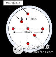
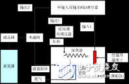
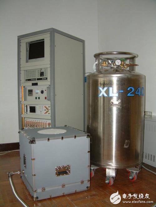
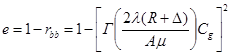
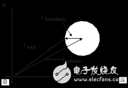
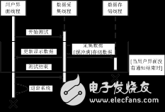
A microwave radiometer is a passive remote sensing instrument used to measure the microwave thermal radiation of an object. Since the microwave radiation signal of the object is a very weak non-coherent signal, the power of this signal is much less than the noise power of the radiometer itself, so the radiometer is essentially a high-sensitivity receiver. In order to overcome the effects of system noise and channel gain drift on the sensitivity, linearity and stability of microwave radiometers, an accurate relationship between the input brightness temperature of the microwave radiometer and the output voltage must be established, known as radiometer calibration. Calibration accuracy will directly affect the radiometer's measurement accuracy. The three types of radiometers, microwave imager, microwave thermometer and microwave hygrometer, have been installed on the “FY-3†meteorological satellite that has been launched. The calibration technology is listed as FY-3 weather satellite. One of the key technologies. The wide-aperture variable-temperature noise source (hereinafter referred to as variable-temperature source) introduced in this paper can provide a variable brightness temperature output in the range of 85K~340K. It achieves the linearity, sensitivity, and sensitivity of microwave radiometers in conjunction with standard cold sources and standard heat sources. Stable ground calibration work. In the second part of this paper, the structure and working principle of the variable temperature source are introduced. The third part is the measurement of the emissivity of the variable temperature source radiator and the related contents of the radiator temperature measurement. Finally, the test results and conclusions of the variable temperature source. The variable temperature source is mainly composed of a wide-aperture radiator, a temperature control device, a temperature measurement system, and a liquid nitrogen container. Figure 1 shows a schematic of a wide-aperture radiator. Radiator processing is as follows: First, a metal substrate similar to the shape of a sharp chamber-shaped wave-absorbing material in a dark room is processed by wire cutting. The diameter of the entire metal substrate is 300 mm, and the metal pyramid arranged above is a pyramid-shaped square cone; After the special process is processed, the metal substrate is further coated with a wave absorbing material; then a temperature measuring sensor is installed. The distribution of 7 Pt25 platinum resistance sensors for temperature measurement is shown in Fig. 2. Figure 1 Schematic diagram of a wide-aperture radiator Figure 2 Distribution of Temperature Sensors for Temperature Measurement The variable temperature source temperature control method is to complete the control of the heating current of the temperature control body and the liquid nitrogen flow used for cooling according to the external temperature setting requirements, ie, the dual PID control loop, as shown in FIG. 3 . The temperature regulating body communicates with the self-pressurized liquid nitrogen tank, and there is a regularly distributed path in the temperature regulating body, which facilitates the passage of liquid nitrogen or low-temperature nitrogen gas, thereby reducing the physical temperature of the temperature control body. In addition, multiple heaters are installed inside the temperature control body to increase its physical temperature. The solenoid valves and heaters that control the flow of liquid nitrogen are all accurately regulated by the PID regulator. The PID regulator increases the physical temperature of the temperature control body according to the difference between the input temperature measurement information and the set temperature, adjusting the heater current and the on-off ratio of the solenoid valve controlling the liquid nitrogen flow according to a certain ratio. Drop or stay stable at some point. Figure 3 Variable temperature source temperature control block diagram Figure 4 Photo source of variable temperature source The instrument equipments contained in the vertical cabinet are from top to bottom: IPC monitor, IPC chassis, temperature control chassis, FLUKE 1590 super resistance thermometer, and FLUKE 2590 multi-channel scanning switch. The white foam window on the upper surface of the grey box in front of the picture is the bright temperature radiation surface of the variable temperature source. The purpose of the foam here is mainly to insulate and prevent condensation of water vapour on the surface of the radiator. 3.1 Radiator Emissivity Measurement According to Planck's law and Rayleigh-Kings formula, the bright temperature of the radiation of objects in the microwave and millimeter wave band According to the Friis formula and related correction formulas, the emissivity of the wide-aperture radiator shown in Fig. 1 can be calculated using formula (2). (2) The meaning of each parameter in formula (2) is as follows: Radiative emissivity measurement can be divided into backward voltage reflection coefficient measurements ( Figure 5 shows a block diagram of the scalar network analyzer (SNA) measuring the back-to-back voltage reflection coefficient. By sliding the radiator back and forth on the heavy-load straight slide rail, the reflection coefficient of the antenna itself and the reflection coefficient of the radiator can be separated. Figure 5 Schematic diagram of SNA measurement backward voltage reflection coefficient Figure 6 shows a composite vector of several reflection coefficients. Among them, the reflection from the discontinuity between the antenna and the free space impedance can be considered as a fixed reflection vector. When the measured radiator slides back and forth in the antenna axial direction, the trajectory of the resultant vector is a center point of the antenna vector. Round shape. The radius of this circle is the backward voltage reflection coefficient of the radiator under test. Figure 6 Reflection coefficient measurement combined vector 3.2 Temperature Measurement Temperature measurement system consists of FLUKE1590 super resistance thermometer, FLUKE2590 multi-channel switch, Pt25 platinum resistance thermometer and data acquisition software. The data acquisition software mainly has three function modules: user interface module, data acquisition module, and data storage module. The main classes are CServerDlg, CDlgSensorCfg, CDlgHTPage, CDlgCTPage, CDlgVTPage, CSensors, CSensor, and CNiVisaSession. The main data structures are _CAL_DATA and _TEMPERATURE_DATA. When the above three modules need to run simultaneously, if they are designed in single-threaded mode, when any one module is working, the other two modules are in pause state. To solve this problem, the software uses three different threads for each of these three parts. To achieve, so that the three modules run independently, through the message and the necessary synchronization mechanism to complete the interaction of information. The relationship is shown in Figure 7. Among them, the user interface module is used for displaying the temperature measurement result, responding to the user input at the same time, completing the interaction with the user, and transferring the interaction result with the user to the other two modules; the data acquisition module is used for the collection and processing of the temperature measurement data; The data storage module is used to store the data collected by the data collection module as a data file on the local hard disk. Figure 7 UML model diagram of data acquisition software Table 1 shows the measurement indicators of the variable temperature source we have developed and the comparison with several major technical indicators of the UK variable temperature source. The large difference in the emissivity between the two parties comes from whether the scattering correction factor Cg in formula (2) is taken into account when calculating the emissivity. Table 1 Measurement results and comparison of variable temperature source technical indicators Parameter Country China United Kingdom Temperature range 85K to 340K Variable 85K to 340K variable Temperature uniformity 0.2K or less 0.2K Temperature stability 0.15K/10min0.15K/10min Emissivity "0.995 or more" 0.99999 Radiator diameter 300mm-- This article describes a wide-diameter variable-temperature noise source, the device can provide 85K ~ 340K variable brightness temperature output in the range of 10GHz ~ 90GHz, the output brightness temperature expansion uncertainty is less than 1K. This device and related technologies have been successfully applied to the microwave radiometer ground calibration test carried by the FY-3 series of satellites.
ZGAR AZ CC Disposable
ZGAR electronic cigarette uses high-tech R&D, food grade disposable pod device and high-quality raw material. All package designs are Original IP. Our designer team is from Hong Kong. We have very high requirements for product quality, flavors taste and packaging design. The E-liquid is imported, materials are food grade, and assembly plant is medical-grade dust-free workshops.
Our products include disposable e-cigarettes, rechargeable e-cigarettes, rechargreable disposable vape pen, and various of flavors of cigarette cartridges. From 600puffs to 5000puffs, ZGAR bar Disposable offer high-tech R&D, E-cigarette improves battery capacity, We offer various of flavors and support customization. And printing designs can be customized. We have our own professional team and competitive quotations for any OEM or ODM works.
We supply OEM rechargeable disposable vape pen,OEM disposable electronic cigarette,ODM disposable vape pen,ODM disposable electronic cigarette,OEM/ODM vape pen e-cigarette,OEM/ODM atomizer device.
Disposable E-cigarette, ODM disposable electronic cigarette, vape pen atomizer , Device E-cig, OEM disposable electronic cigarette ZGAR INTERNATIONAL(HK)CO., LIMITED , https://www.szvape-pen.com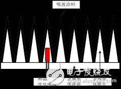
 Can be expressed as the emissivity of the object
  The product of its physical temperature T, as shown in equation (1), is the theoretical basis for the development of variable temperature sources.
  (1)
(1) 
 As the power reflection coefficient of the radiator,
  Is the backward voltage reflection coefficient of the radiator at a certain distance,
  For the working wavelength,
  To measure the effective area of ​​the antenna,
  To measure the near field gain correction factor of the antenna,
  The vertical distance from the center of the antenna mouth to the radiator,
  The distance from the center of the antenna mouth surface to the center of its phase, Cg, is the diffusion correction factor of the radiator. ) and Scatter Correction Factor Measurement (Cg) in two parts. The measurement of backscattered reflectance coefficients is based on the spatial sliding load method; the scatter correction factor measurement is similar to the measurement of the scattering cross section of a dual-station radar. The transmitting and receiving antennas are located on a curved slide, and the energy scattered in the space is measured and integrated. Then divide the integral value of the metal plate to obtain the scattering correction factor of the radiator.
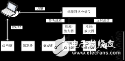


1 Introduction