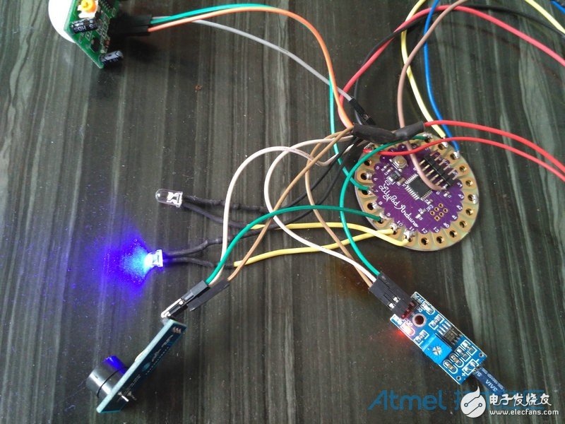
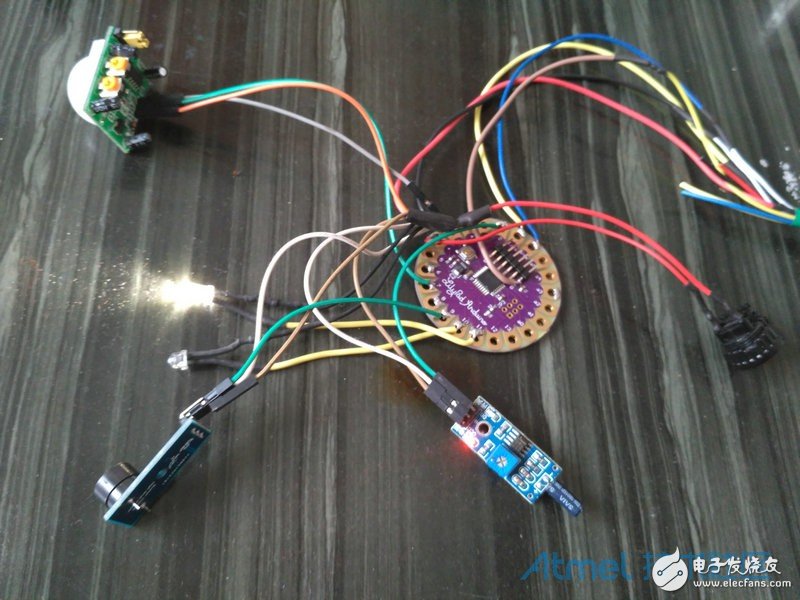
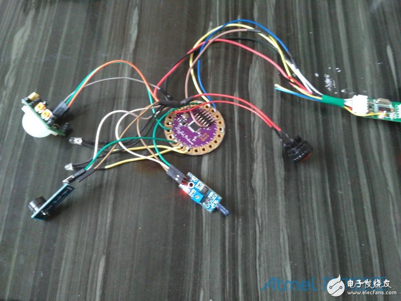
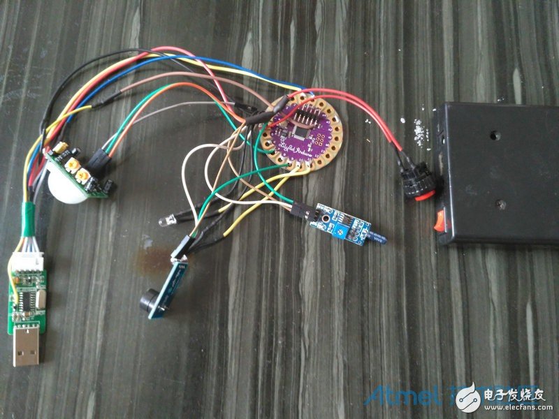
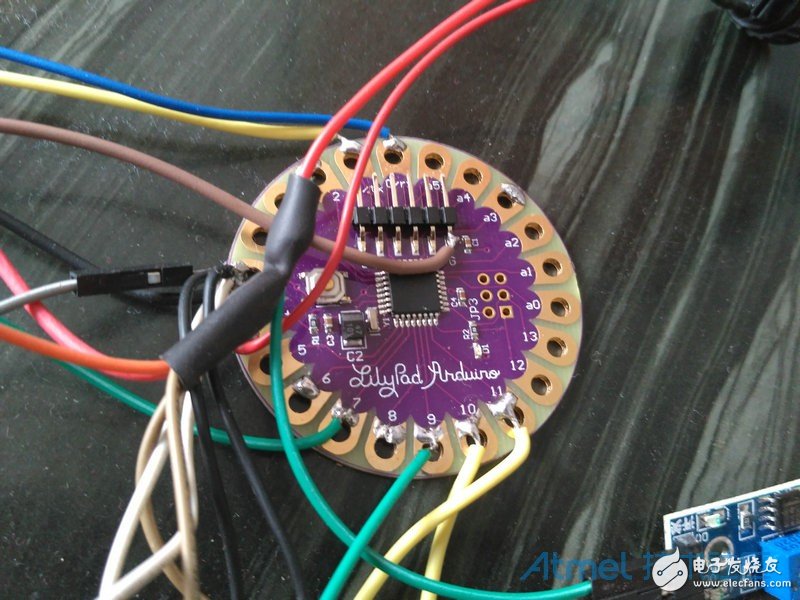
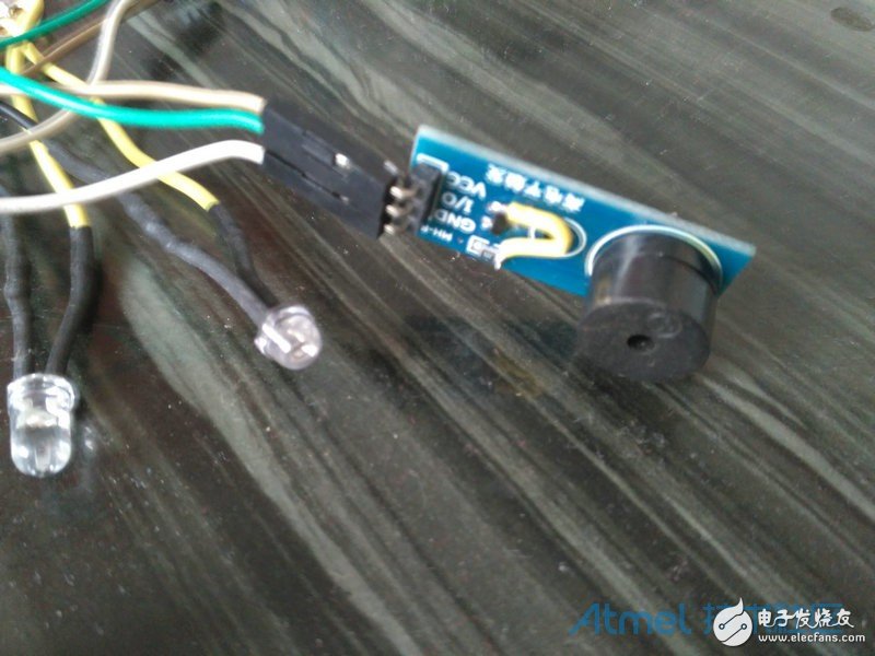
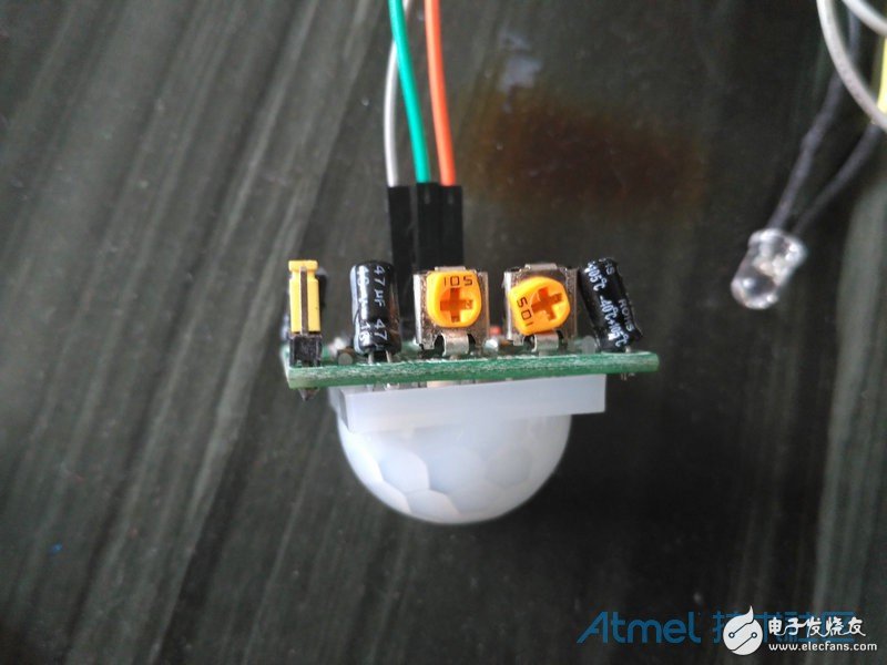
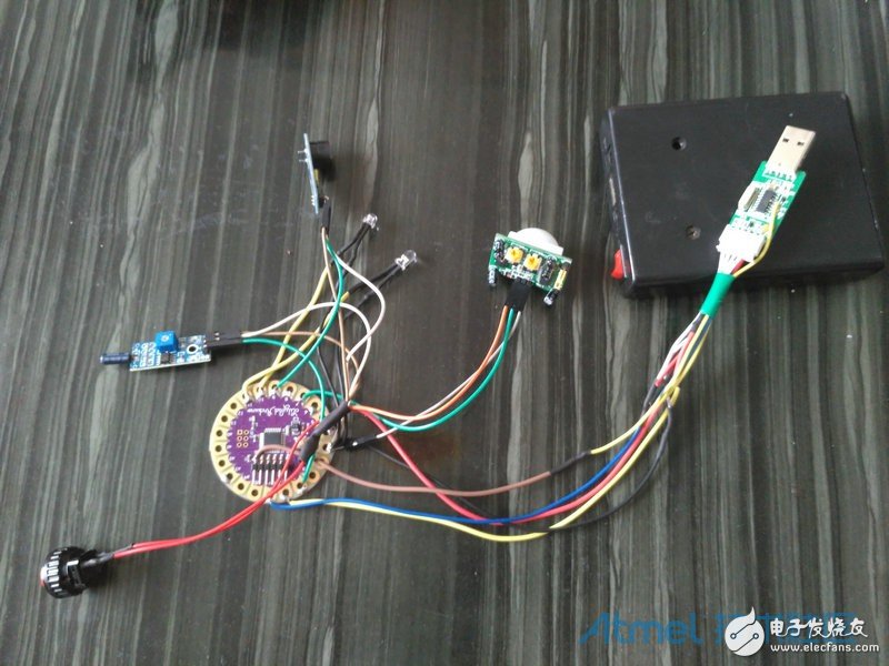
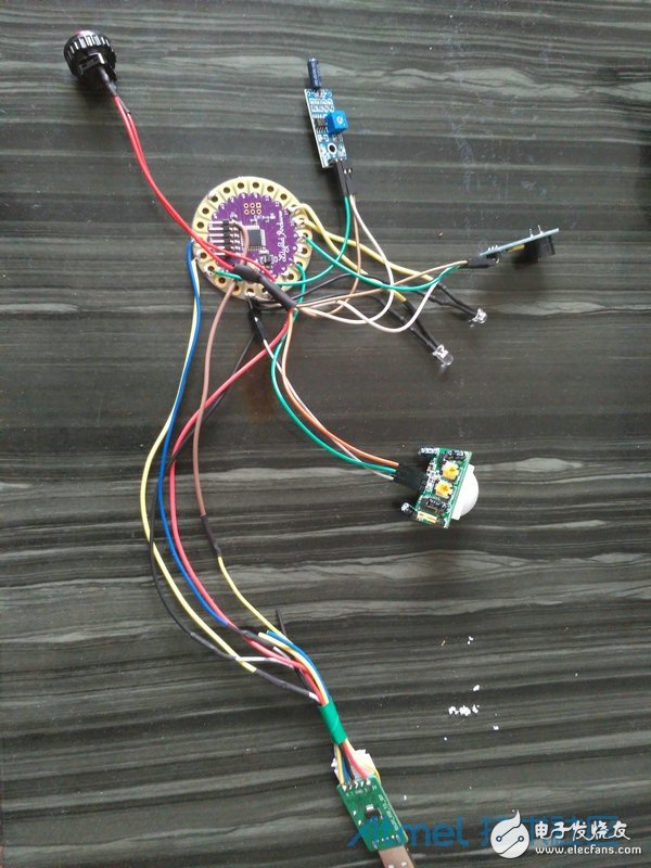
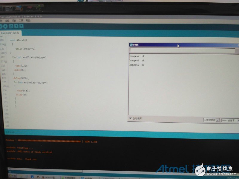
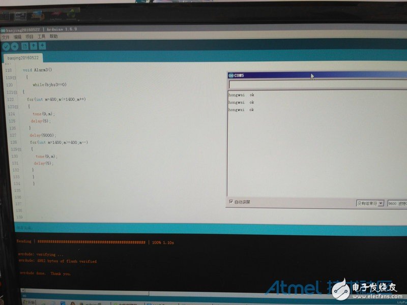
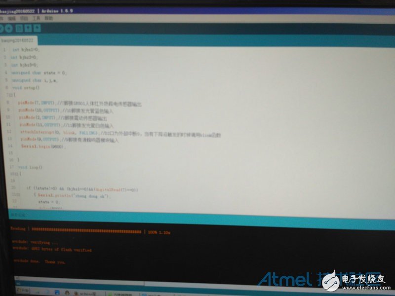
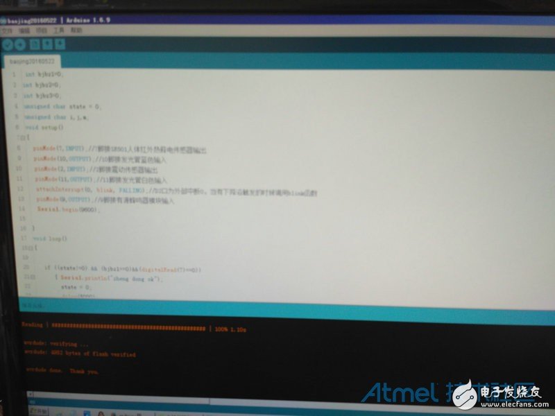
My basic idea is to use the Arduino LilyPad real-time sensor and the human body's infrared sensor module to signal the active buzzer module after a trigger signal. Something used: Arduino LilyPad Board 1 Vibration sensor 1 Human body infrared sensor module 1 Active buzzer module 1 White luminous tube 1 Blue luminous tube 1 Push button switch 1 USB to TTL board 1 Charging treasure 1 The program has been modified several times. The current calculation is stereotyped. The trigger signal of the vibration sensor is detected, and the delay is 5 seconds. The buzzer emits a frequency alarm sound, and the white LED emits light. The trigger signal of the human body infrared sensing module is detected, the delay is 5 seconds, the buzzer emits the second kind of frequency alarm sound, and the blue light emitting tube emits light; the trigger signal of the human body infrared sensing module and the trigger signal of the vibration sensor are detected, After a delay of 5 seconds, the buzzer emits a third kind of frequency alarm sound, and the blue light tube and the white light tube emit light; the delay of 5 seconds is convenient for the owner to open the door to close the alarm; once the sound and light alarm triggers, the cycle will not stop. Unless the owner turns off the power or the charging battery is not enough. The following is a physical photo: Code: Int bjbz1=0; Int bjbz2=0; Int bjbz3=0; Unsigned char state = 0; Unsigned char i,j,m; Void setup() { pinMode (7, INPUT); / / 7 foot connected SR501 human body infrared pyroelectric sensor output pinMode (10, OUTPUT); / /10 foot connected to the light tube blue input pinMode (2, INPUT); / / 2 foot connected to the vibration sensor output pinMode (11, OUTPUT); / / 11 foot connected to the light tube white input attachInterrupt(0, blink, FALLING);//D2 port is external interrupt 0, call the bring function when there is a falling edge trigger pinMode (9, OUTPUT); / / 9 foot connected active buzzer module input Serial.begin(9600); } Void loop() { If ((state!=0) && (bjbz1==0)&&(digitalRead(7)==0)) { Serial.println("zheng dong ok"); State = 0; Delay(5000); digitalWrite(11,HIGH); Alarm1(); Delay(3000); noTone(9); Bjbz1=1; } Else { noTone(9); digitalWrite(11,LOW); Bjbz1=0; } If ((digitalRead(7)==1)&& (bjbz2==0) ) { Serial.println("hongwai ok"); If (bjbz2==0) Delay(5000); digitalWrite(10,HIGH); Alarm2() ; Delay(3000); noTone(9); Bjbz2=1; } else { noTone(9); digitalWrite(10,LOW); Bjbz2=0; } If ((state!=0) && (bjbz3==0)&&(digitalRead(7)==1)) { Serial.println("zheng dong and hongwai ok"); If (bjbz3==0) Delay(5000); digitalWrite(11,HIGH); digitalWrite(10,HIGH); Alarm3() ; Delay(3000); noTone(9); Bjbz3=1; } Else { noTone(9); digitalWrite(10,LOW); digitalWrite(11,LOW); Bjbz3=0; } } Void blink()// Digital input sensor falling edge trigger interrupt service function { State++; } Void Alarm1() { While(bjbz1==0) { For(int i=100;i"800;i++) { Tone(9,i); Delay(5); } Delay(5000); For(int i=800;i"=200;i--) {tone(9,i); Delay(5); } Delay(2000); } } Void Alarm2() { While(bjbz2==0) { For(int j=700;j“=1500; j++) { Tone(9,j); Delay(5); } Delay(4000); For(int j=1500;j"=700;j--) { Tone(9,j); Delay(5); } Delay(2000); } } Void Alarm3() { While(bjbz3==0) { For(int m=400;m“=1400;m++) { Tone(9,m); Delay(5); } Delay(5000); For(int m=1400;m》=400;m--) { Tone(9,m); Delay(5); } Delay(2000); } }
The speaker wire harness most are used in automobile, house applicance ,audio,video,radio,fuse wire ,game
machine.Yacenter has experienced QC to check the products in each process,
from developing samples to bulk, to make sure the best quality of goods. Timely
communication with customers is so important during our cooperation.
If you can't find the exact product you
need in
the pictures,please don't go away.Just contact me freely or send your sample
and drawing to us.We will reply you as soon as possible.
Speaker Wire,Custom Speaker Wiring Harness,Speaker Wiring Harness,Car Speaker Wire Harness Dongguan YAC Electric Co,. LTD. , https://www.yacentercns.com