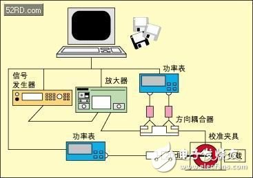
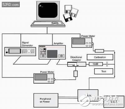
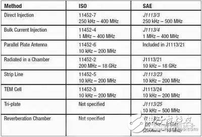
With the increase in electronic components in vehicles, the trend of automakers to outsource components is becoming increasingly apparent. Component manufacturers that undertake the production of electronic components must be responsible for testing their products, and as the interior environment becomes more complex, automotive manufacturers are increasingly demanding component testing. This paper aims to help test engineers choose the best test method by introducing various methods and their advantages and disadvantages of EMI immunity test for automotive electronic components. For many years, electromagnetic interference (EMI) effects have been a concern in modern electronic control systems. Especially in today's automotive industry, vehicles use a number of critical and non-critical (CriTIcal and non-criTIcal) in-vehicle electronic modules, such as engine management modules, anti-lock braking systems, and electrical power steering funcTIons. , in-car entertainment system and thermal control module. At the same time, the electromagnetic environment in which the vehicle is located is also more complicated. The electronics on the car must coexist with the RF transmitter. Some of these transmitters are properly installed and set up (for example, in emergency services vehicles), while others are not. (for example, some factory-installed CB transmitters and car mobile phones). In addition, the vehicle may also enter a strong electromagnetic field generated by some external transmitters, the intensity can reach tens or even hundreds of Ford per meter. The automotive industry has been aware of these problems for many years, and all well-known manufacturers have taken certain measures to reduce the impact of electromagnetic interference by establishing test standards and legislative requirements. Therefore, today's vehicles have strong resistance to such interference. However, EMI has a great impact on the performance of on-board modules, so you must continue to be vigilant. Testing of vehicles and their components is a highly specialized field that has always been done by the manufacturers themselves. In some countries, many vehicle manufacturers will jointly fund professional test labs. With the increasing number of sub-components used in vehicles, the trend of outsourcing of components by automakers is becoming more and more obvious. Therefore, EMC testing has gradually become the responsibility of component manufacturers. A number of different test methods and test levels for overlapping frequencies are described in subsections of the International Standard for Immunity Testing of Automotive Components, such as ISO 11452 (International Organization for Standardization) and SAE J1113 (Institute of Automotive Engineers). Vehicle manufacturers can develop their test requirements based on these general standards without any higher legislative requirements. That is, when an automaker wants to develop component-level test requirements for its component suppliers, he can choose the appropriate amount from a list of test methods, test frequency ranges, and test levels to form his own test criteria. Ultimately, a manufacturer that supplies sub-components to multiple automakers may have to test the same components in the same frequency range using different methods depending on different standards. To meet customer testing needs, component manufacturers can use a range of automotive component test systems designed for the RF test specifications included in ISO 11452 and SAE J1113 to help with their work. These test systems are usually self-contained systems that follow the highest level test specifications specified in all standards. With such a system, many of the test instruments used by component manufacturers when testing multiple standards are the same, thus saving a lot of money. Below we will discuss several RF test methods and some of the test parameters specified in the automotive manufacturer's test requirements, and explore how component manufacturers can build the corresponding test system according to the test needs of different customers, to achieve the purpose of testing only the required projects. To test the RF immunity of an automotive component, RF interference must be applied to it in a manner comparable to how the in-vehicle interference occurs. This introduces the first variable. The car may be exposed to an external field and may carry transmitters and antennas that generate interfering signals, but in any case, the interference field can act directly on where the component is located. For example, when the component is mounted on an open area on or near the dashboard, it creates more interference than when it is installed near the chassis of the vehicle or even in a shielded area inside the engine compartment. many. On the other hand, all electronic modules are connected to the wiring system of the vehicle for the purpose of power supply and signal connection. The wiring device is equivalent to an effective antenna that can be coupled to RF interference, and RF current can be conducted through the connector to the component regardless of where the component is mounted. In view of this, we usually use two test methods: radiation interference test and conducted interference test. All radiation test methods do not apply a calibrated RF field to the device under test, so that RF current and voltage can be introduced into the internal structure of the device, and then these RF currents and voltages will appear in the sensitive device. On the node, causing interference in the electronic circuit. Different methods differ in the way they apply RF fields, and each has its own advantages, disadvantages, and limitations. The simplest way to generate an RF field is to inject energy into an antenna and point it to the device under test (EUT). The antenna converts the RF energy into a radiation field and fills it with the test area. Since high-level RF signals need to be generated over a wide spectrum, in order to avoid interference with other legitimate radio users in the vicinity, the test should be performed in a shielded room. But this will introduce reflections from the walls, which will change the field distribution in the room. In order to solve this problem, it is necessary to perform radio wave silencing on the surface of the shielded room to create an "absorber lined chamber" environment, which in turn greatly increases the cost of the test equipment. The antenna used in the test should have a wide frequency response over the measured frequency range. The test frequency in vehicle testing may range from 10 kHz to 18 GHz, so there are many different types of antennas required (see Figure 1). In addition, the field added to the EUT should be as uniform as possible and well controlled. The field at the time of testing may affect the specifications of the darkroom, so the antenna should not be too close to the EUT, and the directivity should not be too strong, otherwise the resulting field will only be concentrated in one area of ​​the EUT. At the same time, the distance between the antenna and the EUT will cause the mutual inductance to increase, which will increase the control difficulty of the signal added on the antenna. The larger the physical size of the object being measured, the more difficult it is to meet this distance requirement. In addition, according to the formula P = (E · r) 2 / 30 watts (when the antenna has unit gain), the farther the antenna is from the EUT, the greater the power required to reach a given field strength. Note that this formula gives the squared relationship between field strength and distance, that is, when the field strength at a given distance increases from 10 V/m to 20 V/m, the required power is four times the original. Or, when the field strength increases from 10 V/m to 20 V/m, the distance is only a quarter of the original at a given power. The field strength at the EUT position is measured by an isotropic wide-band field sensor. Isotropic is to ensure that the sensor is insensitive to direction, while broadband is to ensure that it can get the correct measurement at different frequencies. According to ISO 11452-3 and SAE J1113/24, the TEM unit is simply a closed transmission line with a certain RF power fed at one end and a load impedance at the other end. As the electromagnetic waves in the transmission line propagate, an electromagnetic field is established between the conductors. TEM (ie, transverse electromagnetic waves) describes the dominant electromagnetic field generated in the active region of such cells. When the length of the transmission line is given, the field strength is uniform over a certain cross-sectional area, and it is easy to measure or calculate. The EUT is placed in the active area of ​​the TEM unit. The TEM unit is generally in the form of a box with a partition surface inside, the wall of the box is used as one end of the transmission line, and the isolation surface (or septum) is used as the other end. The geometry of the TEM cell has a decisive influence on the characteristic impedance of the transmission line. The cabinet is closed and there is no electromagnetic field outside the unit except for a small leak, so this unit can be used in any environment without external shielding. The main disadvantage is its upper frequency limit, which is inversely proportional to its physical size (see Table 1). When the frequency is above this upper limit, higher-order modes begin to appear in the structure of the internal electromagnetic field, and the uniformity of the field, especially at the resonant frequency determined by the exact size of the TEM cell, also begins to deteriorate. The maximum EUT size that the TEM unit can measure is limited by the amount of field strength uniformity available within it, so there is a direct relationship between the maximum EUT size and the highest frequency that can be measured by the unit. The lowest measurement frequency of the TEM unit can go to DC, which is why it differs from the radiation antenna measurement method. These two methods are fundamentally different from the TEM unit method. The TEM cell method is a closed-type measurement method, and the test device used in the strip line method and the three-plane method is an open transmission line. That is to say, when using these two methods, the maximum field is located between the planes, but there is still energy radiated to the outside of the test device, so the test must be performed in a shielded room. Stripline testing is described in both ISO 11452-5 and SAE J1113/23, while the three-plane test is only mentioned in SAE J1113/25. In the stripline test, the component under test is exposed only to the cable assembly that connects it to the associated device and is not exposed to the maximum field strength between the planes. The strip line plane serves as the source conductor of the transmission line, with a 1.5 m cable arrangement placed underneath, and the reference ground plane tested as the other end conductor. The field created by the stripline induces a meridional current in the cable assembly and is then coupled into the EUT. Therefore, the stripline test is almost a mixture of the two methods of radiation field test and conduction test. In the three-plane test device, an active inner conductor is sandwiched between two outer planes, and the resulting impedance can be calculated. The module to be tested is placed between the center conductor and an outer plane, and the other side of the center conductor is left empty. Since the structure of the entire test device is symmetrical, a field strength probe can be placed on the side of the blank that is mirrored to the EUT. As with the TEM unit test, both the stripline test and the three-plane test set have an upper frequency limit limited by their size. When it is equal to or higher than the resonant frequency determined by the size, an uncontrolled electromagnetic field higher order mode is generated. The advantage of these three methods over the radiated antenna method is that with these three methods, only a small amount of power is required to produce a much larger field strength than the radiating antenna method because the field strength is equal to the plane between the conductors. The voltage is divided by the distance between them. The second type of test method is called conducted interference test. It does not need to apply an electromagnetic field where the module under test is placed, but directly applies RF interference to the cable device or the device that accesses the module under test. In this way, as the RF current is transmitted in the circuit structure (for example, a printed circuit board PCB), a current is generated at the junction of the component module and the external device, thereby causing interference in the electronic circuit. Although this method is similar to the radiation field test method, there is no equivalent between the two methods. Therefore, both methods are often used for complete testing, and sometimes the frequency ranges of the two tests overlap. The two coupling methods most commonly used in conducted interference testing are the current injection method (bulk current injecTIon, BCI) and the direct injection method. The former needs to inject interference current into the EUT and control the magnitude of the injection current, while the latter injects power and controls it. The amount of injected power. The BCI method is described in ISO 11452-4 and SAE J1113/4. When this method is used, a current injection probe is placed on the cable device connected to the device under test, and then RF interference is injected into the probe. At this point, the probe acts as the first current transformer and the cable device acts as the second current transformer, so that the RF current flows first in the cable device in a common mode (ie, the current circulates in the same manner on all conductors of the device) ), and then enter the EUT's connection port. The current actually flowing is determined by the common mode impedance of the device at the current injection, and at low frequencies this is almost entirely determined by the impedance of the EUT and associated equipment connected to the other end of the cable assembly to ground. Once the cable length reaches a quarter of a wavelength, the change in impedance becomes important, which may reduce the repeatability of the test (see Figure 2). In addition, because the current injection probe introduces losses, a large driving capability is required to establish a reasonable level of interference on the EUT. Despite this, the BCI method has the great advantage that it is non-invasive because the probe can be simply clamped to any cable that does not exceed its maximum acceptable diameter without any direct cable conductor connection. It also does not affect the working circuit to which the cable is connected. The BCI method has too high requirements for driving capability, and the isolation from related equipment during the testing process is not good. The purpose of the direct injection method is to overcome these two shortcomings of the BCI method. This is done by connecting the test equipment directly to the EUT cable and injecting RF power into the EUT cable through a Broadband Artificial Network (BAN) without interfering with the interface of the EUT with its sensors and loads (see Figure 3). The RF impedance presented to the EUT can be controlled over the range of test frequencies. The BAN can provide at least a blocking impedance of 500 W in the direction of flow to the auxiliary device. The interference signal is directly coupled to the line under test through a DC blocking capacitor. This method is described in ISO 11452-7 and SAE J1113/3. Test parameters for automotive component EMI testing In the EMI test of vehicle components, in addition to the different requirements of different vehicle manufacturers, in addition to the basic methods of introducing interference signals, there are many different parameters. But regardless of how RF interference occurs, these parameters are relevant. Frequency Range Each of the above methods is only applicable to a given frequency range, subject to the limitations of the test method itself and the transducers used. Table 2 lists the applicable frequency ranges published by the various methods discussed in this paper in the corresponding standards. During the test, it is usually necessary to scan the test signal for changes or step changes over the entire frequency range, and monitor the difference between the EUT and its function and performance to obtain the test result. The minimum residence time per test is typically 2 seconds, and if the time constant of the EUT is large, the residence time may be longer. If a software-controlled test signal generator is used, the test signal is usually not scanned over the entire frequency range, but in a stepped manner, so the step size of the frequency step is also defined. The combination of the residence time and the frequency step determines the time it takes to perform a single scan, which in turn determines the time required for the entire test. Amplitude control Regardless of the test method used, the amplitude of the test signal applied to the EUT must be carefully controlled. The method of amplitude control can be divided into two categories according to different principles, one is called closed-loop control method and the other is called open-loop control method. In stripline testing and TEM unit testing, the resulting field can be calculated from known net input power and transmission line parameters. But in addition to these two methods, it is necessary to use the closed-loop method to achieve amplitude control. In the radiated interference test, the unit of the interference signal is volts/meter. In the current injection test, the unit uses milliamps. In the direct power injection test, the unit uses watts. The range of frequencies that apply to different test methods in different standards. With the closed-loop control method, a field strength meter or current monitoring probe constantly monitors the excitation applied to the EUT, thereby adjusting the power to the target value. One problem with this method is that the intervention of the EUT disturbs the electromagnetic field we use as the interference stimulus, so we can't find a field that can correctly reflect the field strength we get and that is universally applicable to all types of EUTs. This problem is especially noticeable when performing radiation interference tests in a microwave darkroom. When the test frequency is such that the EUT size can be compared to the wavelength, the distribution of the field may be greatly reduced at some locations. If the field strength meter is placed in such a position, then when we maintain the required electromagnetic field strength based on the field strength meter reading, it will inevitably cause serious over-testing at the position near the EUT. A similar problem exists in the BCI test. When the common mode input impedance of the EUT resonates with the test signal, maintaining the required current will cause over-testing. In fact, in such an environment, many times the amplifier does not provide the power needed to maintain the specified level, and once the amplifier is overloaded, it will cause more test problems. The open loop method can avoid the above problems. The open loop method is sometimes called the replacement method. When using the open loop method, a signal of a given intensity is first sent to the test equipment for calibration settings. At each frequency, the output power of the amplifier is monitored by an auxiliary power meter, which is recorded when the amplifier output level reaches the target value. Finally, this pre-calibrated power record is rigorously replayed during the actual test. In general, since the measurement of the field or current (volts per meter or milliamps) applied to the EUT is not within the requirements of the test, the open loop method does not measure them, but only monitors them to confirm the system operation. normal. But for the reasons mentioned in the previous section, we are not likely to see the true correct measurement. In the radiated interference test, the calibration setup process requires that a field strength meter be placed at the exact location that the EUT should occupy in the microwave darkroom. In the conducted interference test, the calibration device is a load with a given impedance value, and we measure the power or current at both ends. The power parameters used in the open loop method include the net power, or the difference between the forward power of the input transducer and the reverse power reflected from the transducer. Assuming that there are no other significant losses, this difference is equal to the power actually fed into the EUT. Therefore, when using a direct coupler, two powers must be measured at each frequency. At this time, a power meter can be used to sequentially measure the forward output and the reverse output of the coupler, or two power meters can be simultaneously measured. The net power is used to account for the voltage standing wave ratio (VSWR) of the transducer because the VSWR will change when the EUT is introduced. However, when the EUT is closely matched to the test set, the forward power required to maintain the net power may vary significantly relative to the power required for calibration. In order to avoid over-testing, the forward power that is increased to maintain the required net power cannot exceed 2 dB. Even if 2 dB does not meet the requirements, it should not continue to increase, and this can only be recorded in the test report. Modulation frequency and modulation depth All RF immunity tests require CW (unregulated continuous wave) and modulated AM signals on the EUT at each frequency, while the EUT's response is generally more susceptible to modulated interference. In general, the modulation signals specified in the test standard are sine waves with a modulation depth of 80% and a frequency of 1 kHz. However, there are also individual vehicle manufacturers that may have different requirements. The purpose of defining modulation parameters is to specify a constant peak level for AM and CW testing. This is different from the commercial (IEC 61000-4 series) RF immunity test. In the commercial RF immunity test, the peak power of the modulated signal is 5.3 dB higher than the unmodulated signal. In the test with constant peak level, the modulated signal power with a modulation depth of 80% is only 0.407 times of the unmodulated signal power. The application of this signal is clearly defined in ISO 11452: ◠At each frequency point, the signal strength is increased linearly or logarithically until the signal strength meets the requirements (the open loop method means that the net power meets the requirements, and the closed loop law means that the level of the test signal strictly meets the requirements), according to +2 dB The criteria monitor forward power. ◠Apply the modulated signal as required and keep the test signal hold time equal to the EUT minimum response time. ◠Slowly reduce the test signal strength and then test the next frequency. Monitoring EUT When applying a test signal, the EUT's response must be monitored and compared to the performance criteria it should meet to determine if the device under test passes the test. Since the functions of different EUTs and the performance criteria that need to be met are different, it is impossible to generalize these monitoring methods. But if the test software can automate some or all of the monitoring work, the whole test will be simpler and more reliable. The monitoring process may simply measure and record the output voltage at each frequency point, or it may involve special EUT software that can flag when the test finds an error. After the test was completed and the EUT's response was observed, the test engineer's work was only half completed. He or she must then create a test report in the format specified by the vehicle manufacturer. A component manufacturer may provide products for multiple vehicle manufacturers, so for the same set of tests, component manufacturers may need to submit test reports in multiple formats. Some packages include an optional report generation module that provides standard report templates tailored to different vehicle manufacturers. Although test engineers are mostly enjoying the testing process, few people like to write test reports, so the managers of all test labs understand that providing test reports to customers is the most difficult task. With the automatic report generation software module, not only do test engineers no longer have to bear the pain of writing test reports, but customers' requirements can be met more quickly. In summary, although the EMC test of components in the automotive industry contains many variable parameters, we can still efficiently perform tests covering a wide frequency range for different vehicle manufacturers. This paper introduces the various methods used in component testing in the automotive industry, and summarizes the advantages and disadvantages of various methods. By reading this article, test engineers can better choose test methods to meet customer needs. A manual pulse generator (MPG) is a device normally associated with computer numerically controlled machinery or other devices involved in positioning. It usually consists of a rotating knob that generates electrical pulses that are sent to an equipment controller. The controller will then move the piece of equipment a predetermined distance for each pulse. Manual Pulse Generator,Handwheel MPG CNC,Electric Pulse Generator,Signal Pulse Generator Jilin Lander Intelligent Technology Co., Ltd , https://www.landerintelligent.com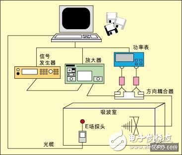
The CNC handheld controller MPG Pendant with x1, x10, x100 selectable. It is equipped with our popular machined MPG unit, 4,5,6 axis and scale selector, emergency stop and reset button.