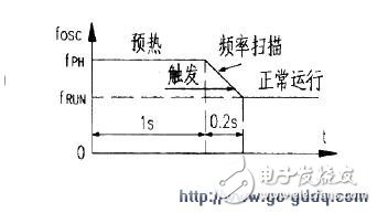
FM2822 is a tunable Fluorescent Lamp electronic ballast application-specific integrated circuit (ASIC) with independent property rights. 16-pin DIP package, dimming phase detection scheme, by changing the pulse width and frequency to achieve lamp power adjustment, thus changing the lamp brightness, to achieve energy-saving purposes. As shown in the figure below, L1 and C1 and C2 form an EMI filter. The gate drivers inside the IC's 9-pin (G1) and (11)-pin (G2) and the external transformer T1 and the half-bridge switches V1 and V2 form a half. Bridge inverter circuit, T2 primary inductance L2-1 and C13 form LC series resonant circuit, R12, R13, R14 and D7, C12 make up the lamp voltage detection circuit, T3, R16, R17 and R18, R7 respectively make up the lamp current phase Sampling and lamp current sampling circuit, R1, R2 and R3, R4, RP1, C4 form a dimming circuit. The circuit works as follows: 1. Startup After the system is powered on, the full-wave rectified output charges C5 via R5, R6, and D6. When the voltage on C5 is charged above 11V, the oscillation circuit starts to oscillate. The half-bridge generates a high-frequency output. The high-frequency signal is coupled via C10, diode D6 rectification, and C5 and C6 filtering to provide the operating current for the VDD pin of the IC. The VDD pin voltage is clamped at 15.6V by the internal zener diode. 2. Preheat and trigger (Lighting) The warm-up time tPH is determined by the 7-capacity CP. The preheat frequency fPH is determined by the resistor RP on the 6-pin. When the warm-up is completed, the frequency sweep mode is entered and the oscillator frequency is shifted from the preheat frequency fPH to the normal operating frequency fRUN (= fmin), as shown in the right figure. The rate of frequency decrease is determined by the CP. When the frequency is close to the resonant frequency of the load, a high-voltage pulse of 1000 Vpp or more is applied to both ends of the lamp at C13 to cause the lamp to break down and be illuminated. The lamp trigger time (frequency sweep time) is 20% of tPH, ie 0.2s. Once the light is on, it enters the operating mode. The operating mode frequency fRUN is determined by (13) the on-pin resistance RF and the 5-pin capacitance CF (approximately 40 kHz). 3. Dimming (15) Pin (IT1) input lamp current sampling signal and 2 pin (VL) input lamp voltage sampling signal are multiplied in the internal multiplier, output from pin 1 and filtered by external RC filter circuit In addition to high frequency components. The output current at pin 1 depends on the product signal of the lamp current and the lamp voltage signal, which forms the power closed-loop feedback for dimming control. 3 feet (DIM) effective input Dimming DC voltage can be changed from 0V ~ 4V, lamp power adjustment range is 2% ~ 100%. 4. Abnormal state protection 1) Over-voltage protection: If the lamp leaks or the cathode deactivates the lamp, the lamp will not light up. An over-voltage will be generated and detected by the 2 (VL) pin of the IC. The system will stop oscillation and enter the low level. Power standby. 2) Capacitive mode protection: If the lamp cannot be turned on or the lamp voltage is too high, a non-zero voltage switch will appear on the half-bridge, and it will work in capacitive mode, resulting in a great loss of the power MOSFET in the half-bridge, even Will be damaged. Once this happens, the IC's 4 (RIND) pin will detect that the main loop current is ahead of the voltage, putting the system into standstill standby mode. 3) End-of-life (EOL) protection: At the end of lamp life, lamp rectification will occur, causing damage or damage to the ballast. (14) Foot (EOL) Built-in window comparators of +1V and -1V, as long as the detection input on pin (14) exceeds the window range, the system immediately enters stop-and-standstill mode. The EOL function is not used in Figure 1, so connect pin (14) to ground. With appropriate changes to some component values, the FM2822 can drive different types of lamps. Lighting SHENZHEN CHONDEKUAI TECHNOLOGY CO.LTD , https://www.szsiheyi.com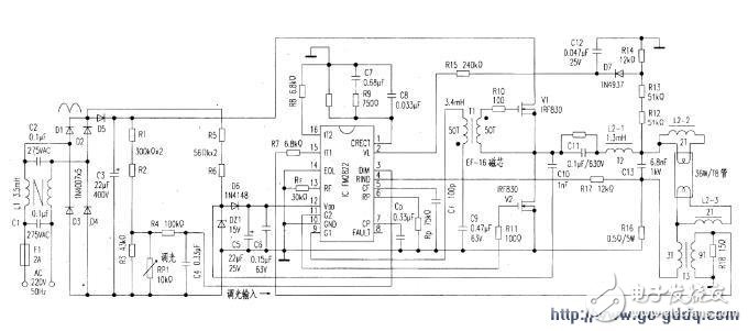
When the voltage-controlled oscillator starts to oscillate, the preheat frequency FPH (=fmax) is output. Since the fPH is much higher than the resonant frequency of the load LC (ie, L2-1 and C13) circuits, the ballast only provides the current heating filament, and there is no high voltage on the lamp that can break the lamp.