Laptop Stand Amazon Basics,Laptop Stand Amazon Basics Aluminum,Laptop Stand Amazon Basics Ventilated,Laptop Stand Amazon Choice,etc.
Shenzhen Chengrong Technology Co.ltd is a high-quality enterprise specializing in metal stamping and CNC production for 12 years. The company mainly aims at the R&D, production and sales of Notebook Laptop Stands and Mobile Phone Stands. From the mold design and processing to machining and product surface oxidation, spraying treatment etc ,integration can fully meet the various processing needs of customers. Have a complete and scientific quality management system, strength and product quality are recognized and trusted by the industry, to meet changing economic and social needs .
Laptop Stand Amazon Basics,Laptop Stand Amazon Basics Aluminum,Laptop Stand Amazon Basics Ventilated,Laptop Stand Amazon Choice Shenzhen ChengRong Technology Co.,Ltd. , https://www.laptopstandsupplier.com
1 Working principle
The basic method for achieving frame synchronization is to insert a set of frame synchronization code groups with a special code pattern into a predetermined time slot at the sending end, that is, a frame synchronization code time slot. At the receiving end, the auto-correlation of the synchronization code is used to determine the synchronization position of the frame. Frame synchronization code groups can be inserted centrally or scattered. For the decentralized frame synchronization code insertion method, the working principle is similar to the centralized insertion method. The following uses the centralized insertion of frame synchronization code as an example to illustrate the working principle of frame synchronization.
The frame synchronization process has a search state, a check state and a synchronization state. The state transition diagram is shown in Figure 1. 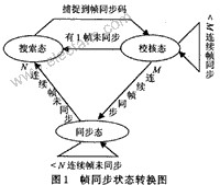
In the search state, at the start of data reception or when the frame is not synchronized, frame synchronization enters the search state. Look for the frame synchronization code (111101000) in the data stream; when the data stream is the same as the frame synchronization code, it indicates that a synchronization frame header has been searched; you can start to enter the frame synchronization check state.
In order to prevent false synchronization from appearing in the check state, the frame synchronization code must be confirmed again after skipping 1 frame length after finding the first group of synchronization codes. If it is confirmed that the synchronization is correct through the M frame synchronization codes continuously, the system immediately shifts to the synchronization state; otherwise, there is a false synchronization; it returns to the search state. From the first search to the frame synchronization header to the M frame that enters the synchronization state, it is called the rear guard time.
Synchronized frame synchronization is in the synchronized state; if continuous N frame synchronization is correct, it will remain in the synchronized state. Considering that the received data stream frame synchronization code may be subject to external interference and there is an error code, in the synchronization state, only consecutive N frames lose the synchronization code before entering the out-of-synchronization state and returning to the search state. The N frame time is called the forward guard time. Due to the forward protection time, although a frame synchronization code error occurs during reception, the system does not immediately go out of sync. This can reduce the possibility of getting out of sync due to bit errors.
2 Frame synchronization
Our VHDL language has realized the design of frame synchronization. The design procedure is as follows:
First define the relevant parameters:
type state_type is (s0, s1, s2);
// System state (search state, check state, synchronization state)
constant syn_code: bit_vector: = "110100"; // frame synchronization code
constant syn_code_length: integer: = 6; // frame synchronization code length
constant max_m: integer: = 2; // number of front protection frames
constant max_n: integer: = 3; // number of rear protection frames
variable m: integer range 0 to max_m: = 0;
// Continuously obtain the synchronization code number
variable n: integer range 0 to max_n: = 0;
// Number of consecutive lost synchronization codes
variable reg: bit_vector (syn_code_length downto 1);
//Shift Register
variable state: state_type: = s0; // initial state
Secondly, send the received data to the shift register and detect the data synchronization code of the sender. When the system is in a different state, its state transition is as follows:
(1) In the search state, its VHDL language is described as follows:
if (clk'event and clk = '1') then
case state is
when so => ​​if (reg = syn_code) then // Search state
state: = sl;
m: = 1,
else
m: = 0;
end if;
(2) In the verification state, its VHDL language is described as follows
if (clk'event and clk = '1') then
case state is
when s1 => if (reg = syn_code) then // Check the state
m: = m + 1;
if (m = max_m) then
state: = s2;
m: = O;
end if;
else
state: = s0;
m: = 0;
end if;
(3) In the synchronous state, its VHDL language is described as follows:
if (clk'event and clk = '1') then
case state is
when s2 => if (reg = syn_code) then // synchronization state
n: = 0;
else
n: = n + 1;
if (n = max_n) then
state: = s0;
n: = Os
end if
end if
3 System simulation
Assume that the synchronization code is 110100, the frame length is 14, the front protection is 2 frames, the rear protection is 3 frames, and the input data data is:
010 11010001010100 010 11010001010100 1010001010100 01010101010100 11010001010100 10000001010100 10000001010100 10000001010100 10
The simulated waveform of the output syn is shown in Figure 2.
It can be seen from Figure 2 that the system is in the search state at the beginning. When the system acquires the synchronization code, it enters the verification state; when the system acquires the synchronization code twice in succession, the system enters the synchronization state. In the synchronization state, the system only confirms the out-of-synchronization when it loses the frame synchronization code three times in a row, and enters the search state again. In specific applications, the synchronization code, frame length, front and rear protection time in the program can be adjusted according to actual needs, so that the system is in the best working state. 
4 Conclusion
Because VHDL has a relatively independent description of the design, the designer can understand the structure of the hardware without knowing the design goals. This design method, which integrates design, simulation and synthesis, can effectively shorten the circuit design cycle, reduce possible errors, and reduce development costs. It will play an increasingly important role in modern digital systems in the future. effect. Using VHDL to design digital systems is convenient and simple, and has good portability and maintainability. It represents the trend of modern digital system design.


In the digital communication network, frame synchronization is the most important part of synchronous multiplexing equipment. It includes the generation of frame synchronization codes and the identification of frame synchronization codes. Among them, the structure of the frame synchronization recognition circuit at the receiving end has a major influence on the synchronization performance.