description: This article describes a power conversion circuit unit in a commercially available finder circuit. It uses a single-ended flyback structure with TL494 as the control Ic. The control IC in the power supply of most desktop computers uses TL494 (half bridge). This circuit has a battery current limit and an antenna short-circuit protection function. When a short circuit is encountered, the power will be automatically turned off. It is equipped with an antenna access indicator to indicate if the antenna is connected. General Purpose Rectifier Bridge
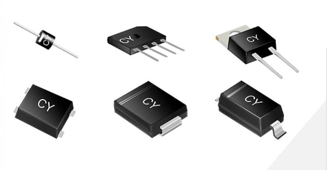
A bridge rectifier provides full-wave rectification from a two-wire AC input, resulting in lower cost and weight as compared to a rectifier with a 3-wire input from a transformer with a center-tapped secondary winding.
Our company mainly produces diodes, which are sold overseas.Has a stable source of customers, product quality by customers trust.
Our products are the ideal choice of printed circuit board, we have reliable low-cost construction technology, product price cost-effective, welcome to come to consult.
Bridge Rectifiers,GBU General Purpose Rectifier Bridge,General purpose Rectifier diodes,General Purpose Bridge Rectifiers Changzhou Changyuan Electronic Co., Ltd. , https://www.cydiode.com
This circuit is suitable for almost all brands of receiver motherboards (including some of the nine motherboards).
Pin 1 of the TL494 is the output voltage feedback input, and pin (16) is the power consumption current feedback input. Q2 and Q3 are drive tubes. T1 is a switching transformer, 5 feet and 6 feet are the same name end, and Q4 is a power MOS tube. Q1 is a switch tube for short-circuit protection. When the antenna has a short-circuit fault, Q1 will be turned on from turn-off, LED1 will be on, and also the U1 pin 4 will be pulled up and stopped. Q5 is a switch tube (in horizontal polarization) for indicating the state of the antenna connected to eight. This function can detect whether the antenna system is short-circuited or open. J1 is a 4PIN cable plug that connects to the motherboard's power input socket.
In amateur conditions, other components can be selected in the following way: The transformer core is EE22 and can be removed from the transformer on the receiver's original power board. Q4 can be removed from the old computer motherboard. D3, D4 (fast recovery diode), D5 (SCHOTTKY diode) and 4PIN strip plugs can also be removed from the original power strip of the receiver. The input supply voltage of this circuit ranges from 8v to 15v. This board is also suitable for being installed in the Zhongjiu machine, and changed to a DC machine. It is equipped with a small antenna and a small LCD screen to be watched in the wild. 
