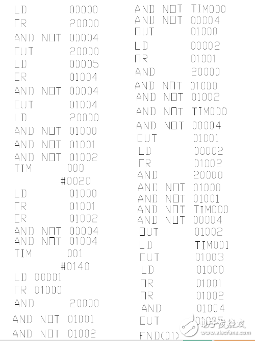
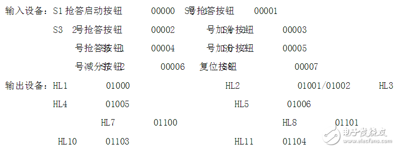
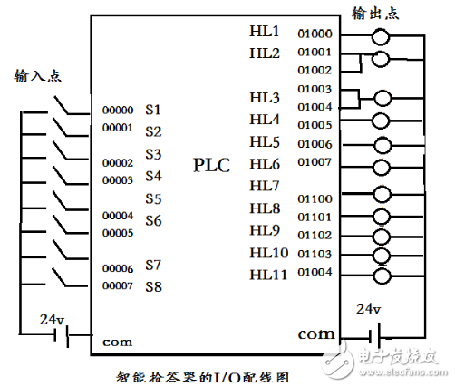
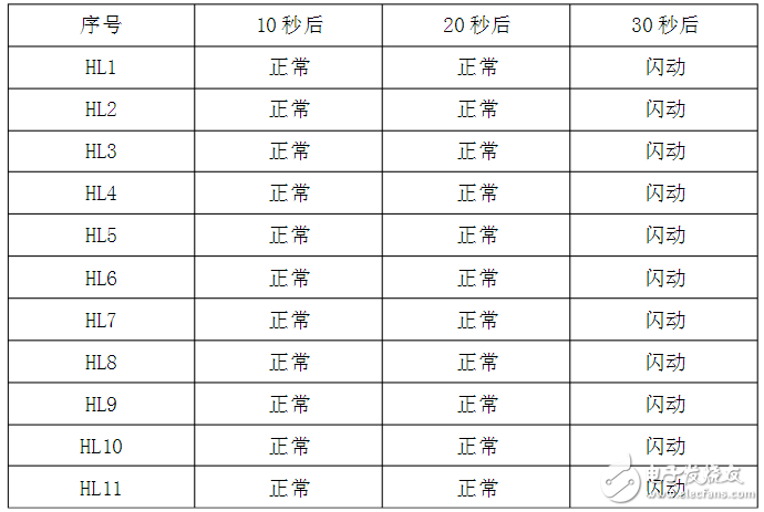
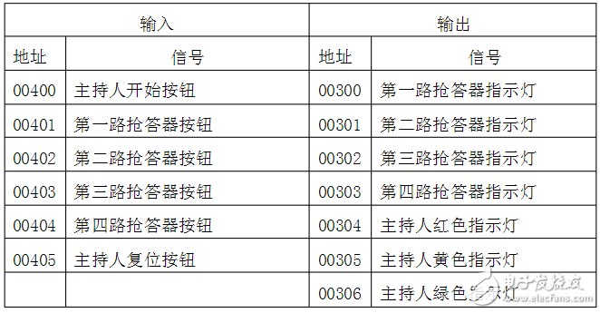
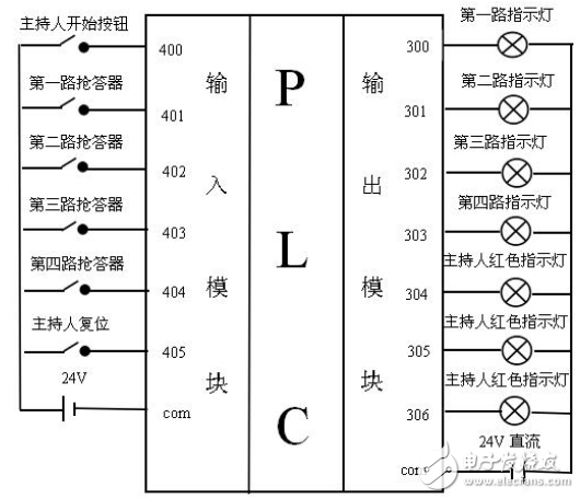
The answering device is designed to realize the electrical device that can accurately determine the responder, as literally. In the knowledge contest, cultural and recreational activities (competition events), the seat number of the respondent can be accurately, fairly and intuitively determined. Better promote the sense of competition of various groups, let the players experience the pressure of the battlefield. The traditional responder only judges the success or foul player number, and can't show the time of each player's answer. Now the responder can use data to explain the accuracy and fairness of the ruling results. The game has greatly increased the entertainment, but also more fair and just. The addition of wireless responders is a major reform in the history of responders. Design a three-group responder device, the host controls the game through the buttons of the console. In order to make the evaluation of the game more transparent, and in order to facilitate the audience to understand the record of each group, the responder device should set the necessary display, the function requirements of the responder are as follows: 1 Before the game starts or the next topic is announced, the host has to press the reset button once to turn off all the indicators. 2 In order to control the game time, the answer to the question must be completed within 14 seconds, and the timeout is based on the error. When the host announces the title and presses the powerful button, the contestant has two seconds to answer the question. If no one answers the answer for more than two seconds, the title is invalidated and the answer is invalid. Press the answer button within two seconds, then the answering indicator light on the console is on, and the answer is valid. When the time is 14 seconds, the answering light is off; 3 The button on the button is pressed first, the indicator on the desktop is on, and the indicator on the button after pressing the button is off; 4 If the answer is correct, when the host presses the correct button of the console, one of them plays a small piece of music; the other is that a small prize is popped up from the reorganized prize box; 5 Groups that do not have the right to answer are unlikely to receive extra points. At the end of the game, the winners will be judged by the number of prizes. I port: 00000----SB host control grab button (start) button 00001----SB1 first group group answer button 00002----SB2 second group group answer button 00003----SB3 third group answer Button 00004-----SB4 Host Control Reset Button (Stop) Button 00005----SB5 Host Control Reward Button (answer correctly) button O port: 01000 Output first group rush signal 01001 Output second group rush signal 01002 Output third group rush signal 01003 Output timeout alarm signal 01004 Output answer correct signal 01005 Output bonus signal External wiring electrical task assignment: KA1 controls the answering group one, and simultaneously locks the second and third KA2 control and answering group 2, and locks the first and third KA3 control and answering group three, and locks the first and second KA4 control alarm lights KA5. Signal light A KA6 control gift box B PLC control responder handheld programmer input program as shown below: 1. Before the host presses the answer button, the player answers in advance and the indicator light 1 or 2 on the player's table flashes for 4 seconds, then goes out. 2. Within 15 seconds after the host presses the answer button, if the player does not answer, the indicator light on the host's desk is extinguished, and the answer is invalid. 3. After the host presses the answer button, one of the players will answer the question first, and the indicator light on the table will be on, and the other player cannot answer the indicator light on the table. 4. After the contestant has answered the answer, the answer must be completed within 40 seconds. If the answer is not completed within 40 seconds, the indicator light on the desk will be off, the indicator light on the host's desk will be on, and will automatically go out after 15 seconds. 5. Before each answer, the host presses the reset switch, so that the indicator light on each player's desk is off. 6. After the player answers correctly, the host presses the bonus button, and the corresponding player group score light is on, the answer is wrong, and the score button is pressed, the corresponding player group score light is off. After the host presses the reset button, the addition and subtraction indicator does not change. Based on the I/O wiring diagram above, we used OMRON's software for programming. Mainly using Omron's programming software for programming, mainly adding time and counting procedures, the program is shown in Appendix 1; In the team's intelligent responder design process, after our hardware was finished, we transferred the program to the PLC and found some problems during the software debugging process: (1) When the hardware and PLC are connected during the debugging process, the connection between the input point and the output point appears to be unresponsive. After checking the hardware of our group and querying all aspects of the data, we finally find the input point. When intervening, there was an error in the power wiring of the public end. After debugging, the expected requirements were finally met. (2) After the hardware design of the team is completed, we will transfer the program to the PLC for debugging. It is found that the status of each signal light is as shown in the following figure at different time periods: This time, the PLC four-way responder designed by me can be used for four or four teams to answer each other at the same time. Each responder is equipped with a green 24V DC indicator and a green jog button to complete. The reset button and start button of the responder are controlled by the moderator, and the host has three display lights. (1) The responder is identified by an indicator light. Before the host presses the start button, the player presses the responder button. At this time, the player's green indicator light is on, and the host's red indicator light is on, indicating that the player who lights up promptly answers the foul. Then the question belongs to the player who cancels the early answer and deducts the corresponding score. The host presses the reset button to prepare the answer for the next question. (2) The responder has a timing function. The host presses the start button and the host's green light indicates that the user can start to answer. If someone answers in 20 seconds, the player's green light indicates that the player has successfully answered. The responder has a self-locking function, that is, at the same time, there are a number of players who rush to answer. Only the player who is the first to answer the green light is illuminated. After the other, the player's light is still extinguished. If no one answers the host's yellow light in 20 seconds, the flashing light indicates that the reminder time is approaching. If there is still no player in the 25 seconds, the host is red. The red light is on behalf of the question. No one answered and the question is invalid. After a second, if a player presses the responder button, the player's green indicator light is still off. After the host announces that the title is invalid, press the reset button to prepare for the next question. The I/O of the PLC is the connection point between the input module and the output module used by the PLC and the different devices. I have designed 6 input points and 7 output points in the responder. In addition, there is a common terminal in the wiring. Since my maximum input and output are seven, I chose the eight-bit input and output module of the OMRON C200He model. The connection of the PLC device is like adding a PLC module to a complete circuit that we usually do experiments. The number of input modules and output modules of different types of PLCs is also different. Since its wiring is only connected to the input and output of the common terminal and the power supply, its wiring is particularly small, which is also an advantage of the PLC compared with the complicated wiring of the conventional relay. The wiring of the 6-bit input and 7-bit output I designed is shown below: 200*300mm Anti-Blue Light Film
The Imported Anti-Blue Light For ipad is made of high-quality imported TPU material. It is precisely cut by the Screen Protector Cutting Machine. Protect your device screen from scratches and cracks. The flexible TPU Screen Protector can completely cover the iPad screen, providing the maximum protection for the iPad.
Advanced blue light blocking technology can protect your eyes, can effectively filter blue light, prevent glare, reduce eye fatigue, and help you fall asleep better.
Super clear and transparent, will not reduce the screen brightness, maintain the original screen brightness, and reduce eye fatigue.
The Protective Film adopts an oleophobic and waterproof coating, which can ensure anti-fingerprint, waterproof, dustproof and no air bubbles. Moreover, it is sensitive to touch, bringing natural touch, fast response and flawless precise touch.
If you want to know more about Imported Anti-Blue Light For ipad products, please click product details to view the parameters, models, pictures, prices and other information about Imported Anti-Blue Light For ipad products.
Whether you are a group or an individual, we will try our best to provide you with accurate and comprehensive information about Imported Anti-Blue Light For ipad!
Imported Anti-Blue Light Protective Film, Imported Anti-Blue Screen Protective Film, Imported Anti-Blue Screen Protector, Imported Anti-Blue Light Screen Protector Shenzhen Jianjiantong Technology Co., Ltd. , https://www.tpuscreenprotector.com