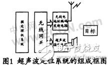
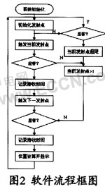
Advances in technologies such as sensor technology, MEMS, modern networks and radio communications have driven the emergence and development of wireless sensor networks. Wireless sensor networks have broad application prospects and can be applied to military defense, industrial and agricultural control, urban management, biomedical, environmental positioning, disaster relief, remote control of hazardous areas, and many other fields. The principle of ultrasonic positioning is similar to that of a radio positioning system, except that the attenuation of the ultrasonic waves in the air is large and only applies to a small range. Ultrasonic waves travel in air only a few tens of meters. The short-range ultrasonic ranging system has been applied in practice, and the ranging accuracy is centimeter. The ultrasonic positioning system can be used for positioning of moving objects in places such as unmanned workshops. 1.1 echo signal The principle of the ultrasonic detection signal analysis system is to realize the analog-to-digital conversion of the ultrasonic detection electrical signal by the mutual coordination of the ultrasonic detector and the signal sampling device and the computer, and complete the storage of the detection data, and the computer utilizes the quantized echo signal data according to the data. The theory and technology are handled accordingly. Ultrasonic testing is a physical means that uses the nature of ultrasound to determine the distance of a target. It is a non-destructive detection method for judging the position of an object based on the characteristics of the interface reflection when the ultrasonic wave moves in the detection area. A common technique in ultrasonic testing is to send an ultrasonic short pulse to an object to be measured. When the sound wave returns from the discontinuous structure or boundary of the object, the echo waveform is obtained. When the wave touches the front wall of the object, a narrow-band random wave with several oscillation periods is generated, which is called the start wave. At the same time, a part of the ultrasonic wave infiltrates into the object to be measured, touches the back wall surface of the object, and an oscillating echo is obtained. , called the bottom wave. The distance of the object can be calculated by using the time interval between the start and bottom waves and the speed of the known sound wave in the object. Similarly, when the sound wave touches a discontinuous target position such as a hole or an impurity in the object to be measured, an echo is generated, and information on the target position, such as the approximate positional property of the target position in the detection area, is obtained. 1.2 Model establishment What is processed in ultrasonic detection is an oscillating wave, which has the characteristics of a narrow-band random signal. The traditional ultrasonic testing equipment adopts the hardware detection method to extract the echo envelope, and the detection accuracy and the precise positioning of the main peak position cannot be guaranteed. Since the target echo position directly determines the measurement accuracy, especially for moving targets, how to accurately determine the echo position is the key to the technology. The signal acquisition system introduced in this paper includes the sensor signal acquisition design and the hardware design and construction of information transfer between the sensor and MOTE. The ultrasonic sensor is characterized by its good directionality and can achieve centimeter-level positioning accuracy. In some demanding positioning systems such as DPEG and Crickets, the ultrasonic sensor-based ranging method is adopted. The working principle of the ultrasonic sensor is: the signal time emits a beam of sound at zero time, assuming that the sensor receives the returned ultrasonic wave after the elapse of time t, according to the formula s=vt, the value v is 34000 cm/s, and the actual ultrasonic transmission time The unit is milliseconds (mm), after conversion is 10-6s, then According to this formula, the distance value s can be obtained, which is related to the sensor's timer and is a sample value closely related to the hardware device. In the system, assuming that the timer of the ultrasonic sensor is 16 bits, then 216=65536, 65536/58=1129, that is, the range that can be positioned is about 11H. In practice, we find that there is a linear relationship between the collected data and the actual distance. The distance that can be detected by the 16-bit timer is only 1.46m, which is a catastrophic limitation for the target positioning system. In this case, the time precision is used to improve the working range of the ultrasonic wave, and the time precision is reduced to 1/3 of the original, and the actual detection range is correspondingly increased by three times to 4.8 m. After actual inspection, it is proved that the design can be achieved and has a good and accurate ranging effect. The system consists of ultrasonic sensors, node gateways, wireless networks, notebooks and line remote control toy cars. As shown in Figure 1. The data of the wireless sensor network is transmitted to the computer through the gateway, and the service program parses the data content and processes it. A part of the content is stored in the data array after the event is classified, and is used as an analysis query. The other part is only used for data fusion between different sensors, that is, the sensor's own position is discarded by the sensor node after communication control, because the sensor node has limited storage space and energy, and a large amount of data storage is not only It wastes space and costs batteries. The database can select the data for location estimation according to the needs, and then modify the parameters such as wind direction, obstacles, ground fluctuations and other factors to determine the position information of the target in the detection area. The back-end system communicates with the wireless sensor through the wireless gateway. In addition, these messages need to notify the program module responsible for the user interface part to visually display the targeted content. Ultrasonic positioning systems differ from radio positioning in their implementation. Radio signals at different transmission points can be distinguished by different frequencies, and ultrasonic systems are difficult to implement, so there must be a way to distinguish the ultrasonic signals of the respective transmission points. We use a radio-trigger circuit with address coding to trigger each transmit point. Take the ultrasonic positioning system with fixed transmission point and main body as an example. The main body portion is composed of a microprocessor circuit, an ultrasonic receiving circuit and a radio code trigger circuit; the transmitting point portion is composed of an ultrasonic transmitting circuit and a radio code receiving circuit. The working process of the system first selects the address of the transmitting point to be triggered by the microprocessor, starts the transmitting circuit and starts timing. If the signal is received within a given time, the distance from the subject to the transmitting point is calculated from the delay time. Compared to ultrasound, the transmission time of radio waves is negligible; if no signal is received within a given time, the distance from the subject to the transmission point is considered to have exceeded the acceptable distance. After receiving sufficient transmission point signals, the position coordinates of the subject can be calculated from the distance from the subject to each of the transmission points. Since the propagation speed of ultrasonic waves in the air varies with environmental conditions, in order to improve the measurement accuracy, the measurement results need to be corrected. The MICA2 is connected to the ultrasonic sensor through a 51-array interface, and the ultrasonic sensor power supply is supplied through an external battery pack. MICA2's data processing unit uses Atmel's Atmega128L microcontroller, which uses a low-power CMOS process to produce a RISC-based 8-bit microcontroller. It is the most powerful microcontroller in the AVR family. The AVR core connects 32 working registers and instruction sets, and all working registers are directly connected to the ALU, which realizes the operation of accessing two independent registers while executing a single instruction in one clock cycle. This structure improves. The code efficiency is about 10 times higher than that of the ordinary one. Atmega128L has a wealth of resources and low power consumption. There are 128KB of program Flash, 4KB of data SRAM, and E2PROM which can be expanded to 64KB. In addition, there are eight 10-bit ADC channels, two 8-bit and two 16-bit hardware timer/counters, and can operate in a variety of different modes; eight PWM channels, programmable watchdog timers, and on-chip Oscillator, on-chip analog comparator UART, SPI, I2C bus interface; in addition to the normal operating mode, the JTAG interface has six different levels of low-power operation modes, each with different power consumption. MICA2's data transmission unit module consists of a low-power, short-distance ZigBee-compliant wireless communication module CC2420 for high-integration industrial RF transceivers. The MAC layer and PHY layer protocols of the node conform to the 802.15.4 specification, and the MAC layer uses an ESMA-CA-based mechanism. The chip requires few external components to ensure the validity and reliability of short-range communication. The data transmission unit module supports data transmission rate up to 250kbit/s, which can realize multi-point to multi-point rapid networking. The system is small in size, low in cost and low in power consumption. It is suitable for long-term power supply of batteries, with hardware encryption, security and reliability. The network is flexible and resistant to damage. The software system arranges the designed target positioning system on the actual physical hardware and conducts relevant experimental research. The software flow of the application system is shown in Figure 2. In the initial stage, all nodes are in working state, and the node grouping component selects the duty node to monitor the coverage area; when the duty node locates the event, wakes up the adjacent node to collect data, and the node aggregates the collected data to the head node, and the head node performs preliminary Processing to reduce routing congestion caused by erroneous data transmission to the gateway; the gateway transmits data received from the underlying layer to a base station with strong processing capabilities to estimate the approximate location of the event. In the communication process of the network node, the idle listening of the node when there is no work task consumes quite valuable energy resources; at the same time, the wireless signal has congestion, crosstalk, congestion caused by local message collection during the forwarding process, etc. These issues must be considered in the design of network communication control structures. In order to improve the scalability and adaptability of the system, multiple system components including node grouping, energy management, routing, time synchronization and location estimation are used to facilitate further modification and improvement of the system. Compared with the current layer structure of the Internet network, the wireless sensor network system is generally divided into a physical layer, a wireless link layer, a routing layer, and an application layer, and the layer and layer communicate messages through the interface. At present, the transmission layer is not used by the sensor network, mainly because the traditional message confirmation will cause huge loss of energy of the wireless sensor network, and the sensor network data transmission amount is huge, and is not sensitive to a small amount of lost data, so the transmission layer is in the wireless sensor. The importance of the network is not great. Wireless sensor networks have limited node energy, low data transmission rates, and poor reliability and security. Moreover, during the operation of the system, the node may move in, move out, or fail due to exhaustion of energy, positional movement, etc., thereby causing changes in the network topology and the communication link control structure. In order to maximize the lifetime of the wireless sensor network, the network communication control structure should try to satisfy the following conditions: When the system is in the idle listening state, leave a few nodes to maintain the basic link and make other nodes go to sleep; because the reliability of the nodes is relatively high. Poor, need to ensure the redundancy of the backbone link; the data sent by a large number of nodes is a arduous task for the entire network, effectively using data fusion, distributed processing and other technologies can reduce redundant data and reduce the number of wireless communications Improve scalability and robustness, adapt to changes in node migration, removal or failure. In applications, the energy consumption of wireless sensor network nodes is closely related to the way they are used in the communication process. In the actual environment, through the continuous positioning of the set network coverage area, it is found that the accurate prediction rate of the event is high in the network coverage, and the event false alarm rate is very low, which means that in practice, although the node The correct data is sent, but the data that may be sent at the next moment is wrong. This also explains the necessity of taking certain measures to limit the false positive rate. For the target positioning system, real-time performance is another important point of concern. If the system can not feedback the processing results of the network system in time, the perfect calculation result is meaningless. In theory, the delay of the system is the decisive factor. The ultrasonic positioning system can be used for a range of contactless positioning with a positioning accuracy of up to 1 cm. Since the propagation of ultrasonic waves is greatly affected by the environment, it is not recommended for outdoor use. In practical applications, the application circuit can be appropriately modified according to the environment and specific requirements. For example, the encoded signal can be directly added to the ultrasonic signal, and such a system can be directly used for object recognition. In order to increase the receiving sensitivity, a reflecting device similar to a radar antenna can also be used. In this paper, the echo signal is processed to reduce the influence of noise, and the initial work of ultrasonic signal processing is well completed. The established mathematical model of ultrasonic echo signal processing is easy to implement; the target positioning accuracy is high, which avoids the shortcomings of the traditional analog detector error, and provides a reference for the accuracy positioning of dangerous target positions. China leading manufacturers and suppliers of DC Support Capacitors,DC Capacitor, and we are specialize in Electrolytic capacitor,High Voltage Capacitor, etc.DC Support Capacitors DC Support Capacitors,DC Capacitor,Electrolytic Capacitor,High Voltage Capacitor YANGZHOU POSITIONING TECH CO., LTD. , https://www.cnchipmicro.com