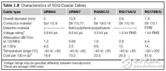
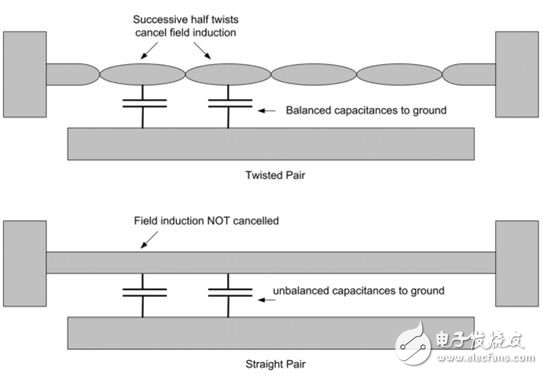
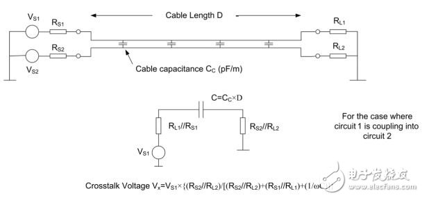
In addition to some special applications, such as high-frequency antenna feeder may use balanced cable, RF signal transmission cable is almost always coaxial cable. The outstanding property of coaxial cable is that the magnetic field that the signal propagates along the cable is confined inside the cable (Figure 1.21) and the interaction with the external environment is therefore kept to a minimum. The text in the figure from left to right: sheath, shield or outer conductor, dielectric, inner conductor, magnetic field is confined within the outer conductor. Figure 1.21 Coaxial cable Another useful property is that the characteristic impedance of the coaxial cable is easily defined and maintained. This is important for RF applications because the cable length in these applications will generally exceed the transmission signal wavelength. Section 1.3 will discuss the general properties of the transmission line - where coaxial is a special type. The parameters commonly seen in the coaxial parameter specification are: ◠Characteristic impedance (Zo): The common standard is 50Ω. This value can be well balanced in terms of mechanical properties and circuit ease of use. The 75Ω and 93Ω standards are common in video and data systems. Any other impedance must be considered as a special type of impedance. ◠Dielectric material. Dielectric materials affect various properties of the cable, including Zo, attenuation, voltage handling, physical properties, and temperature range. Solid polyethylene or polyethylene is a standard material. Partial dielectric insulation properties of honeycombed polyethylene are provided by air gaps, which can provide lighter weight and lower attenuation loss, but are more prone to physical deformation than solid materials. The rated operating temperature for these two materials is 85°C. Polytetrafluoroethylene (PTFE) materials are suitable for higher temperature (200°C) and lower loss applications but at a much higher price. ◠Conductor material. Copper is commonly used. Electroplated silver is also sometimes used, which enhances high-frequency conductivity through the skin effect, or electroplates copper onto strands to enhance strength. The inner conductor may be a single strand or multiple strands. When cables are required for flexibility, it is best to use multiple strands. The outer conductor is usually a copper braid, also for flexibility. Taping coverage affects high frequency attenuation and shielding effects. For special applications that do not require flexibility, hard external conductors can be used. ◠Rated voltage. Thicker cables usually have higher voltage ratings and less attenuation. You cannot easily associate the rated voltage with the power handling capability unless the cable matches its characteristic impedance. If the cables do not match, a voltage standing wave is generated, which in turn produces a peak voltage at some special location along the cable. This value is higher than the value derived from the power/impedance relationship. ◠Decay. The loss characteristics of dielectrics and conductors cause the attenuation to increase with increasing frequency and distance. Therefore, the attenuation data generally provides a value for every 10 meters of the discrete frequency point from which you can find the attenuation value at your operating frequency point. Loss of cable can easily make you crazy, especially when you use long cables to transmit wide bandwidth signals and forget about an additional few dB of loss margin at the end. Coaxial cables currently on the market are divided into two standards: the US MIL-C-17 standard for RG/U (Radio Government, Universal) and the British BS 2316 standard for the UR-M (Uniradio) series. The international standard is IEC 60096. Table 1.8 shows some common 50Ω cable comparison data. One word warning: Never confuse audio cables with shields and RF coaxial cables. Their braiding and dielectric materials are very different. The Zo of the audio cable is indefinite, and the attenuation at high frequencies is very large. If you try to use it to feed RF signals, then you don't receive much signal at the end of the cable! On the other hand, RF coaxial cable can be used to carry audio signals. Twisted pair should be given special care, because it is particularly effective and convenient in reducing magnetic and capacitive interference coupling. Twisting the two wires together ensures a uniform distribution of capacitance. The capacitance to ground and the capacitance to the external source are balanced. This means that the common-mode capacitive coupling is also balanced, so high common-mode rejection can be achieved. Figure 1.22 compares a twisted pair with a non-twisted pair (straight pair), but it should be noted that if your problem is already common-mode capacitive coupling, then it is not helpful to twist the wire. To solve this problem, you need to use shielding technology. Figure 1.22: The advantages of twisted pair The text in the figure is from top to bottom: Continuous semi-twisting can cancel magnetic field induction, balanced capacitance to ground, twisted pair, magnetic field induction cannot be cancelled, unbalanced capacitance to ground, linear twisting method to reduce low frequency electromagnetic coupling The most useful aspect is because it can reduce the area of ​​the magnetic ring to almost zero. Each half-twist will invert the sense direction, so assuming the external magnetic field is uniform, then two consecutive semi-twist will cancel out the interaction between the cable and the magnetic field. Effective loop coupling is now reduced to a small area on both ends of the cable pair, plus a small residual interaction due to magnetic field inhomogeneity and cable twisting irregularities. Assuming that the terminal area is contained in the magnetic field, the number of strands per unit length is not important: usually about 8-16 turns per foot (26 to 50 turns per meter). Figure 1.23 compares the magnetic field attenuation versus frequency for a 22-AWG twisted pair with a 22-AWG parallel line spaced 0.032 inches apart. Figure 1.23 Magnetic field attenuation of twisted pairs. (Source: RBCowdell's "Exploring the Secrets of Twisted Pairs" in the 1979 IEEE EMC Symposium, p. 183) Another advantage of twisting a pair of wires together is to support fully reproducible characteristic impedances. When coupled with bulk shielding, common-mode capacitive coupling can be reduced. Such a cable is ideal for high-speed data communications because it reduces both radiated noise and minimizes induced interference. When more than one signal in the same cable bundle is to be transmitted at any distance, the mutual coupling between the wires will cause one portion of one signal to be fed to the other signal, and vice versa. This phenomenon is called crosstalk. Strictly speaking, crosstalk is not only a cable phenomenon, but also any unwanted interaction between nominally uncoupled channels. This coupling may be dominated by a capacitor, it may be dominated by an inductor, or it may be due to a transmission line phenomenon. When the cable can be seen as a lumped component (in contrast, the high frequency must be seen as a transmission line), the equivalent circuit for low-to-mid-frequency capacitive coupling is shown in Figure 1.24. Figure 1.24: Crosstalk Equivalent Circuit The text in the figure is from top to bottom: cable length D, cable capacitance Cc, for the case where circuit 1 is coupled into circuit 2, crosstalk voltage In the worst case where the capacitive coupling impedance is much lower than the circuit impedance, the crosstalk voltage depends only on the ratio of the circuit impedance. Crosstalk is well-known in the telecommunications and audio fields, such as where originally separate voice channels are transmitted together, one channel is chained into another channel, or separate high frequency stereo channels are combined. Although digital data initially appears to be unaffected by crosstalk, it is also a serious threat to data integrity. Capacitive coupling is almost transparent to fast edges, and the result is that data synchronized to the clock is particularly vulnerable, as shown in Figure 1.25. If the noise immunity of the logic noise is poor, it may result in a serious erroneous clock. Some practical examples (see Figure 1.25) show the nature of the problem. Figure 1.25: Digital Crosstalk Effects The text in the figure is from top to bottom: Signal A, Crosstalk Coupling, Clock B, Corrupted Clock B (a) Two audio circuits with both source and load impedances of 10kΩ use a 2-meter long multicore cable to transmit signals with a capacitance between conductors of 150pF/m. What is the crosstalk ratio at 10kHz? The coupling capacitor CC equals 2m x 150pF/m = 300pF. The impedance at 10kHz is 53kΩ. The source and load impedances in the crosstalk circuit are 10K//10K = 5kΩ in each case. So crosstalk is equal to: 5 K/(5 K + 5 K + 53 K) = 22 dB: This is unacceptable under any circumstances! If the output drive impedance is reduced from 10kΩ to 50Ω, the crosstalk becomes 49/(49 + 49 + 53 K) = 60 dB: this is acceptable for many applications, although it is still true for Hi-Fi. Not acceptable. (b) Two EIA-232 (RS-232) serial data lines use a 16-meter long data cable (not a separate twisted pair) with a core/core capacitance of 108 pF/m. The transmitter and receiver conform to the EIA-232 specification with 300Ω output impedance, 5kΩ input impedance, ±10V swing, and 30 V/μs rise time. What is the magnitude of the interference spike that results from a circuit and on another circuit? The coupling capacitance here is 16 pS = 1728 pF. The current I = C & TImes; dV/dt (1 - exp[-t/RC]) flows from the RC circuit after t seconds from a ramp voltage with a constant dV/dt. In our example, dV/dt=30 V/μs lasts 0.66 μs, the circuit resistance is 567Ω, and the current is 25mA. The peak voltage at the load resistor converted to (300//5 K//5 K) is: 25 & TImes; 10–3 & TImes; 267 = 6.8 V. This is one reason that EIA-232 is not suitable for long distances and high data rates! There are many strategies for crosstalk, which we can see from the above example. These strategies are: ◠Reduce the source and/or load impedance of the circuit. Ideally, the source impedance of the encroaching circuit should be high and the source impedance of the victim circuit should be low. With a certain coupling size, low impedance requires higher capacitance. ◠Reduce the cross-coupling capacitance. Use a shorter cable, or choose a cable with a lower core-to-core capacitance per unit length. It should be noted that this does not solve any problem for fast or high frequency signals because the impedance of the coupling capacitor is less than the circuit impedance. If you use a ribbon cable, sacrifice some space and connect the wires between each signal line to ground; another approach is to use a ribbon cable with a complete ground plane. The best method is to use a separate shield for each circuit. The shield must be grounded, otherwise this method will not bring you any benefit. • Reduce the bandwidth of the signal circuit to the minimum required by the system's data rate or frequency response. As can be seen from (b) above, the coupling effect directly depends on the rise time of the attack signal. Slower rise time means less crosstalk. If you add a capacitor in parallel with the input load resistor (RL2 in Figure 1.24) and form a voltage divider with the core to the core capacitor, you can also reduce the input impedance of high-frequency noise. ◠Use differential transmission. The terrible crosstalk is the main reason for the popularity of differential data standards such as EIA-422 (RS-422) and other update standards at high data rates. It is not necessary to reduce the coupling capacitance when using the pair line, but the crosstalk at this time is injected in the common mode, so it can benefit from the common mode rejection function of the input buffer. The limiting factor of the degree of suppression is the imbalance of the coupling capacitance of each pair of lines. This is why it is recommended to use twisted pair cables for differential data transmission.
Power 12W ,output voltage 3-12V, output current Max 1A, 6 dc tips. We can meet your specific requirement of the products, like label design. The material of this product is PC+ABS. All condition of our product is 100% brand new.
Our products built with input/output overvoltage protection, input/output overcurrent protection, over temperature protection, over power protection and short circuit protection. You can send more details of this product, so that we can offer best service to you!
12W Wall Adapter, 12W Wall Power Supply,12W Power Cord In Wall, 12W Wall Power Adapter Shenzhen Waweis Technology Co., Ltd. , https://www.waweispowerasdapter.com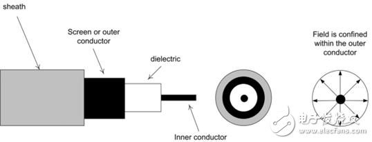
RF cable