With the popularization of the technology system of "integration between heaven and earth" in the communication system, mobile communication is developing towards a seamless coverage. The wide coverage of satellite mobile communication makes it a necessary supplement for ground mobile communication. At present, foreign satellite mobile communication systems include the North American Mobile Satellite (MSAT) system, the Asian Cellular Satellite (ACeS) system, the Thuraya satellite (Thuraya) system, and the International Maritime Satellite (Inmasrsat) system that provides global coverage. Inmasrsat is operated by the International Maritime Organization. There are more than 160 countries using the system and more than 290,000 users. Its fourth-generation system BGAN is the first mobile communication system that provides voice and broadband data to the world through handheld terminals. It is also the first mobile satellite communication system to provide data rate certificates. Therefore, the satellite mobile communication system design and its application model are proposed here. Satellite mobile communication renderings 1 Satellite mobile communication system transmission model In satellite communications, radio waves are affected by many factors during space transmission, such as atmospheric absorption, tropospheric scintillation, rain, snow, etc., will cause different degrees of attenuation, of which the attenuation of the signal by rain is the most serious, so the rain of the satellite link Attenuation characteristics are the main factors that affect the transmission quality and reliability of satellite communication systems. When designing a satellite communication system, necessary measures should be taken to deal with various signal attenuations, and a transmission model should be designed according to the characteristics of the channel. The transmission model of the satellite signal between the satellite and the ground network is shown in Figure 1. 2 Communication system of satellite mobile communication system 2.1 Frame structure The mobile satellite communication system uses the TDMA multiple access method. The physical layer signals are transmitted in the form of TDMA frames. Considering the compatibility with the handheld terminal on the ground GSM network, the frame format is divided into hyperframe (hyperframe) and superframe (superfrAME). Multiframe (mulTIframe), frame (frame), time slot (TImeslot). 2.2 Modulation method Whether it is a business channel or a control channel, this system uses the same modulation method. Unlike the GSM system, this system uses a π / 4-CQPSK (coherent quadrature phase shift keying) modulation mechanism, and its shaping filter uses a roll-off coefficient of 0. Square root of 35 raised cosine function. Compared with the commonly used OPSK modulation method, it can better improve the peak-to-average ratio of the modulated signal, improve the power efficiency of the power amplifier, reduce the out-of-band power radiation, and greatly facilitate the design of the power amplifier. 3 Satellite communication signaling structure Signaling refers to all control information and status information in the communication system except the user's service data. In the satellite mobile communication system, the mobile terminal and the satellite relay transmit information through the S-Um port, and the signaling exchange uses the 3-layer protocol structure shown in FIG. 2 that is, the physical layer (L1) and the data link layer (L2) Compared with the network layer (L3), where the data link layer (L2) uses satellite channels, its channel model is essentially different from the terrestrial GSM system. LAPSat can support both acknowledgment and non-acknowledgement mode data transmission. The L3 protocol layer mainly completes the establishment, maintenance and termination of circuit-switched connections, and provides the necessary support for SMS control and supplementary services. The L3 layer is further subdivided into the following sublayers: radio resource management layer (RR), mobile management layer (MM) and connection management layer (CM), where the connection management layer includes call control (CC) and supplementary services (SS), Short Message Service (SMS). The signaling transmission of the L3 layer is implemented by the protocol control entity. The RR layer and the MM layer also define other functions of the L3 signaling transmission, such as information multiplexing and segmentation. The RR layer and MM layer identify the signal through the information header PD. The specific process is shown in Figure 3. Uplink signal: First, the CM sublayer defines a transmission identifier (TI). As part of the information header, the control information, supplementary information, and short information are added to the MM layer with a TI header, and the transmission function of the MM layer will have different The CC, SS, and SMS information of the transmission identification is multiplexed, and a protocol identification (PD) is added, and the uplink transmission is transmitted to the RR layer. The transmission function of the RR layer transmits different information through their respective accesses according to different PD headers and corresponding channel configurations. The point (SAPI) is transmitted to the corresponding physical channel, and the dual-tone receiving system (DTRS) entity uses the same transmission function to transmit the dual-tone multi-frequency signal (DTMF) to the RR layer entity. The RR entity detects whether the data link connection on the fast associated control channel (FACCH) exists at the access point (SAPI) = 2. If it exists, the data link (DL) connection is used, otherwise it passes the access point (SAPI) ) = 0 for data transmission, and the information is transmitted in the form of bit stream on the various logical channels defined in the physical layer. When the RR connection does not exist, the RR entity terminates the data transmission. Downlink signal: The RR layer divides the information obtained from different access points in the L2 layer according to the protocol identification (PD) header and distributes it to different sub-layers (but the PD header is retained during the division so that the subsequent MM layer can continue to use it). Other RR information and DTRS information are transmitted to the MM layer through the respective access points MNRR-SAP, DTRS-SAP, and then the MM layer recognizes different TIs, and transmits different information to the CM through the respective MM layer access points The various functional sublayers (ie, control service sublayer, supplementary service sublayer, and short message service sublayer). 3.2 Logical channel configuration In the L3 layer protocol stack, signaling is finally transmitted on the physical channel in the form of frames. According to different frequency bands and time slots used by different signaling, the physical channel is divided into multiple logical channels. Unlike the logical channels of the GSM system, satellite mobile communication channels are mainly divided into two categories: satellite service channels (S-TCH) and satellite control channels (S-CCH) used to transmit user-coded voice and data. The satellite service channel (S-TCH) includes a full code rate service channel (S-TCH / F) with an information rate of 24 Kb / s; a half code rate service channel (S-TCH / H) with an information rate of 12 Kb / s; 1/4 code rate control channel (S-TCH / Q), information rate 6 Kb / s; 1/8 code rate control channel, information rate is 3 Kb / s. The channels used can be allocated according to the size of specific voice and data. The satellite control channel (S-CCH) includes a satellite broadcast control channel (S-BCCH), a satellite common control channel (S-CCCH), and a satellite dedicated control channel (S-DCCH). Satellite dedicated control channels include independent control channels and associated control channels. The associated control channel is divided into a slow associated control channel (S-SACCH) and a fast associated control channel (S-FACCH). Usually, it cannot be used independently, but is used together with other control channels. The above three control channels use different frame formats to frame the information. 1) S-BCCH includes synchronization channel (S-SCH), satellite broadcast control channel (S-BCCH), satellite beam broadcast channel (S-BBCH), and mainly transmits signaling such as system information. 2) S-CCCH includes satellite call channel (S-PCH), satellite random access channel (S-RACH), satellite access authorization channel (S-AGCH), etc. This channel mainly transmits signaling such as call request, channel request, signing authority, synchronization channel information, and immediate assignment command. 3) S-DCCH and S-ACCH are mainly used for point-to-point information exchange on the channel, and are transmitted on the channel in a common frame format, mainly transmitting allocation commands, allocation response, channel mode modification and response, encryption mode and response signaling . 510 cartridges,510 vaporizer,CBD THC oil Cartridge,Cannabis Oil vapes,Hemp cbd Vaporizer Shenzhen Yingyuan Technology Co.,ltd , https://www.yingyuanvape.com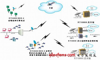
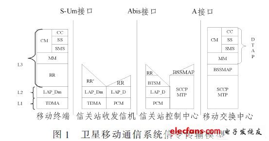
In the figure, the S-Um interface is the signal transmission between the mobile terminal and the ground gateway station using satellite channels through satellite relays: the Abis interface is the interface between the ground gateway station and the transceiver of the gateway station; the A interface is the ground mobile network exchange Interface between the center and the customs station. 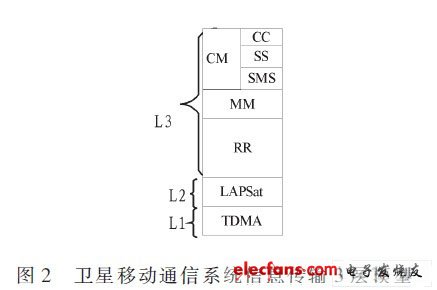
3.1 Network layer protocol stack 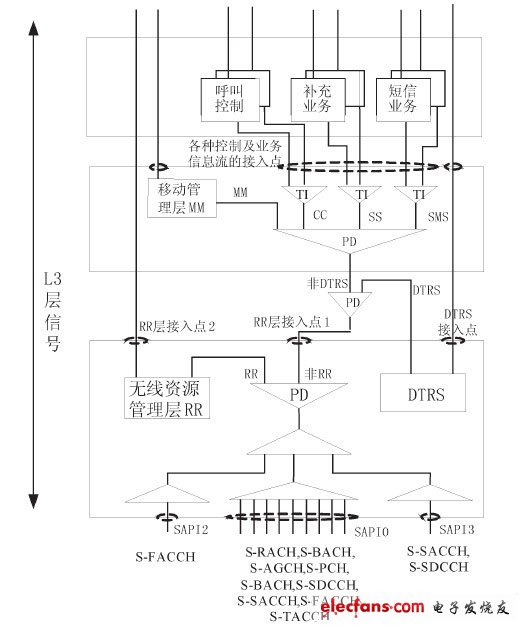
Figure 3 L3 protocol stack of satellite mobile communication