The trigger control circuit consists of trigger switches Sl, S2, resistors Rl, R2 and thyristor (Thyristor) is the abbreviation of thyristor, also known as thyristor rectifier, formerly referred to as thyristor; 1957 United States General Electric developed the world's first thyristor product, which was commercialized in 1958. The thyristor is a PNPN four-layer semiconductor structure with three poles: the anode, the cathode and the gate; the thyristor has the characteristics of a silicon rectifier device. It can work under high voltage and high current conditions, and its working process can be controlled and widely used in electronic circuits such as controllable rectification, AC voltage regulation, non-contact electronic switching, inverter and frequency conversion. The KSPOWER brand H series - 4 in 1 dimmable led driver provides 0-10V 1-10V resistance pwm dimmable constant voltage single output LED Drivers with 5 years warranty. The 4 in 1 LED dimmable driver can make the output wattage of MAX 320W and accept 12Volt, 24Volt, 36Volt and 48Volt output voltage optional. The 12v 24v dimmable led driver is Class 2 Class P rated, and both UL/cUL, FCC CE ENEC GS RoHS Listed and SELV style enclosures. The 4 in 1 led bulb drivers is flicker free design and protections for short circuit, over load, over voltage and over temperature. The 4 in 1 dimmable led transformer use low profile aluminum metal housing with IP65 IP67 rating environment protection for indoor or outdoor use, with junction box makes 0-10V 1-10V pwm dimming led driver the power solutions for LED strips, LED sign, billboard and landscape lighting. Featuring built-in PFC function more than 0.95 and outstanding led dimming performance. led bulb drivers, 24v dimmable led driver, led strip driver, Pwm Driver, led driver enclosure Shenzhenshi Zhenhuan Electronic Co., Ltd , https://www.szzhpower.com
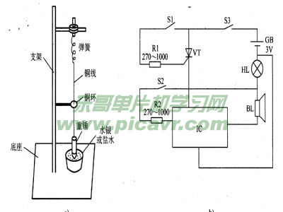
Circuit Operation Principle The home earthquake alarm circuit consists of a trigger control circuit and an acousto-optic alarm circuit, as shown in the figure. 
The sound and light alarm circuit is composed of an indicator light HL, a sound effect integrated circuit IC and a speaker BL.
The trigger switch S2 is a dynamic switch composed of a copper ring and a heavy hammer and a copper wire, and is used to detect a seismic transverse wave; S1 is a moving switch composed of a weight and a mercury (or brine) in the basin, which is used to detect an earthquake. Longitudinal wave. S1 and S2 constitute a detecting device.
When in use, the detection device is installed on the indoor wall or on the window sill. If there is seismic activity, the first pass to the ground, the heavy hammer generates vertical vibration and contacts with mercury (or salt water) (ie, S1 is connected), so that VT is affected. Trigger and turn on, IC powers up, BL emits a short alarm sound, and HL lights up. The transverse wave is transmitted to the ground, and the weight is horizontally displaced, so that the heavy hammer copper wire is in contact with the copper ring (ie, S2 is turned on), and the IC is triggered to change the alarm sound.
Adjust the resistance of Rl, you can change the VT trigger (trigger (is a special stored procedure, its execution is not called by the program, nor is it started manually, but triggered by an event, such as when operating on a table) It performs.) The sensitivity of the conduction changes the sensitivity of the longitudinal wave test.
Adjusting the resistance of R2 can change the sensitivity of the lC trigger, thus changing the sensitivity of the shear wave test (the sensitivity of the longitudinal and shear wave tests should not be too high to avoid false alarms).
Component selection
Rl and R2 use 1/4W metal film resistors or carbon film resistors.
VT selects MCRlO0-6 or BTl69 type thyristor.
IC selects KD9561 type sound effect integrated circuit.
BL uses 0.25W, 8Ω miniature electric speakers.
HL selects the 3.8V red indicator light.
S3 uses a miniature single-pole toggle switch.
The heavy hammer wire uses a copper wire of Φ0.2 mm and a length of 0.5-1 m. The diameter of the copper ring is Φ1.5 mm, and the distance between the copper ring and the weight is 10 cm.