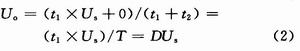
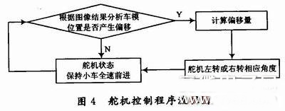
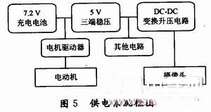
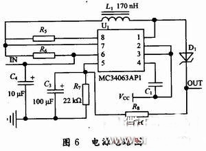
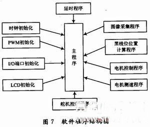
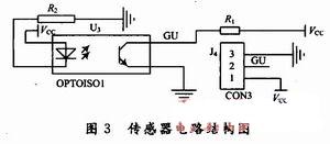
0 Preface This article refers to the address: http:// The wheeled trolley is the main part of the mechanical structure of the smart car, and is composed of structural components such as a body, a wheel, a speed sensor, and a rotating shaft. It also includes a driver that provides power, a camera that collects environmental information, and the like, and comprehensively realizes collecting the state information or external environment information of the car, analyzes and fuses the data of the sensor, and dynamically adjusts the motion state of the car to achieve certain conditions. Self-tracking. The smart car adopts the PID control algorithm, and uses the CCD line type camera as the detection device of the black guide line. After the LM393 is compared, the MCU performs data acquisition and image recognition, thereby enabling path recognition. The motor drive uses the PC33886, which uses a direct-type photoelectric sensor to measure the speed, and displays the relevant information on the LCD liquid crystal display, and uses four button buttons for parameter setting, providing a friendly human-computer interaction interface for on-site debugging. . 1 system frame design The entire car model system can be divided into three parts: the environment image acquisition part, the motor and servo drive part, the central data processing part, and the 16-bit micro controller MC9S12DGl28B as the core control unit. The system block diagram is shown in Figure 1. The power part of the smart car uses a common small permanent magnet DC motor. The drive circuit of this kind of motor is very mature, and it has a driver composed of separate components, and an integrated power integrated drive chip is available. The most important part of a smart car is the brain of a smart car – the central processing system. It is not only responsible for processing the image data sent from the image acquisition part of the environment, but also transforming this information into the drive control signal of the motor, so that the whole vehicle can follow the predetermined rules, which requires the system to have huge data processing capability. . 2 pavement detection module 2.1 Comparison and feasibility analysis of pavement inspection schemes The environment image acquisition part can be realized by using an array infrared probe and a CCD or CMOS image sensor. The former is characterized by low price, simple circuit and convenient application, and has the disadvantages of limited performance, weak adaptability to complex environments, and poor effect. The CCD or COMS image sensor (camera) can compensate for various shortcomings of the array infrared probe. In order to quickly acquire image data and take into account the difficulty of development, a black and white surveillance camera that outputs standard TV video signals will be used in this design. The camera can be combined with the line and field sync signal separation circuit and the A/D conversion circuit of the single chip microcomputer, and the image can be conveniently collected, thereby avoiding the complicated bus protocol and data processing process of the digital camera. 2.2 Hardware Design The LM1881 video sync signal separation chip can extract the timing information of the signal from the camera signal. The synchronous separation circuit of the LM1881 is shown in Figure 2. Pin 2 is the video signal input terminal, the camera signal is input to the LM1881, and pin 3 is the field sync signal output terminal. When the field sync pulse of the camera signal comes, the terminal will become low level, generally maintaining 230μs. Then change back to high level, pin 7 is the odd-even field sync signal output end, when the camera signal is in the odd field, the end is high level, when it is in the even field, it is low level. The alternation of the odd-even field is synchronized with the falling edge of the field sync signal, that is, with the rising edge after the field sync pulse. 3 speed sensor 3.1 Scheme selection (1) Hall sensor with rare earth magnet Advantages: Accurate information, small size, and no increase in rear wheel load. Disadvantages: The gear is close to the main drive motor, which is easily interfered by the magnetic field. It is easy to punch the gear to smooth the gear. (2) Photoelectric sensor Advantages: small size, no increase in rear wheel load, reflective type solution does not require reprocessing of the original device. Disadvantages: Accuracy is limited by the volume of the photocell. (3) Photoelectric encoder Advantages: Accurate and accurate information. Disadvantages: increase rear wheel load and large volume. Comparing the above three schemes, considering the reliability of the system, the main rear wheel rotates the gear as a plastic texture, and the punching is dangerous, and any increase in the weight of the vehicle may affect the speed of the vehicle, and finally the direct photoelectric sensor is decided. 3.2 hardware circuit design The sensor circuit structure is shown in Figure 3. 4 drive section 4.1 Motor drive selection According to the theory of electrical engineering and electric drive, the motor driver must have sufficient current output capability to ensure sufficient driving force. In a comprehensive consideration, the motor driver uses an integrated dedicated power drive integrated circuit to design a driver composed of a separate component (field effect transistor). According to the motor science, the DC motor speed, the expression of n is: Where: U is the armature terminal voltage; I is the armature current; R is the resistance in the armature circuit; φ is the magnetic flux per stage; K is the motor structural parameter. It can be known from the formula (1) that the method of controlling the rotational speed of the direct current motor can be divided into two categories: an excitation control method for controlling the excitation magnetic flux and an armature control method for controlling the armature voltage. Nowadays, the armature voltage control method is used in most applications. This design adopts PWM to realize the speed regulation method of DC motor under the condition of ensuring constant excitation. The average value U of the voltage across the armature winding of the motor. for: Where: the duty ratio D represents the ratio of the time during which the switch is turned on to the period in one period T, and the variation range of D is 0 ≤ D ≤ 1. It can be known from equation (2) that when the power supply voltage Us is constant, the average value Uo of the voltage across the armature depends on the magnitude of the duty ratio D. Changing the value of D also changes the average value of the voltage across the armature. Therefore, the purpose of controlling the motor speed is achieved, that is, PWM modulation is realized. In order to facilitate the material and design convenience, the design selected PC33886 of Freescale Semiconductor. The PC33886 can accept an operating frequency of 20 kHz in PWM speed mode mode; it has overheat, overcurrent, and short circuit protection, and feeds the working state of the device to the microcontroller through a feedback line. 4.2 steering gear control The flow chart of the servo control program is shown in Figure 4. The car model continuously samples the road condition information during the driving process, and judges the road condition of the car model by analyzing the relative position of the car model and the track, and calculates the turning radius. The standard PWM period of all servos is 20 ms, and the rotation angle is up to 90°. When the input pulse width is 0.5 ms, that is, the modulation wave with duty ratio of O.5/20=2.5%, the steering gear turns right. 90°. The relationship between the angle of rotation and the pulse width can be derived as: t=1.5±θ/90 Where: t is the positive pulse width, the unit is: ms; θ is the rotation angle; when the left turn is taken, the addition method is used, and when the right turn is taken, the subtraction method is used. In the specific operation, the period of the PWM modulation wave can be set within a certain range of about 20 ms to make the servo rotate normally. After repeated tests, the output PWM modulation wave period is set to 13 ms. The speed of the running motor and the angle of the steering gear are controlled in software by setting the duty cycle of the PWM wave. 5 power module The motor drive system requires high-power power supply: low internal resistance, high current, and no sensitivity to power supply ripple; single-chip and image acquisition systems require high power quality: low internal resistance, small ripple, and low power consumption. However, it is necessary to guard against the interference generated by the motor during operation. The power supply system block diagram is shown in Figure 5. Since the camera needs a voltage of 9 to 12 V to work properly, the voltage of the rechargeable battery is only 6 to 7.2 V. Therefore, the DC-DC boost circuit becomes a must. The DC-DC voltage conversion uses the MC34063A integrated circuit, which integrates a temperature compensator, a comparator, a dynamic current band-limited duty cycle controllable oscillator, and a high current output driver. The output voltage is directly controlled by two external resistors with an error of 2%. The circuit can be conveniently applied to both boost and buck applications. The circuit schematic is shown in Figure 6. 6 software design The software structure diagram is shown in Figure 7. The entire car automatic identification control process is completed by the program control on the main control chip to complete the entire intelligent control process. After the car is turned on, it will automatically follow the black line track with a certain width. During the driving, the continuously detected black line position information is fed back to the main control chip, and the execution result is fed back to the controller through the main control chip processing, thereby controlling the car. In the forward direction, and through the software to detect the speed of the car and the change information of the button, the result is finally displayed on the LCD display. 7 Conclusion Smart car design involves control, pattern recognition, sensor technology, automotive electronics, electrical, computer, mechanical and other professional fields. The entire design does not use too complicated detection methods or control algorithms, but uses camera image processing technology and classic PID control algorithm, which not only ensures the reliability, stability and rapidity of the system, but also saves cost and workload. In the control algorithm, the PID control ensures the fast and stable system; in the detection method, the design of the camera continuous detection ensures the jitter-free high-speed linear driving and the application of the photocell speed measurement method, which ensures the simple and reliable speed measuring system. . Asic Power Supply,High Power Uninterruptible Power Supply,Active Computer Power Supply,4000W Computer Power Supply Boluo Xurong Electronics Co., Ltd. , https://www.greenleaf-pc.com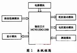

![]()