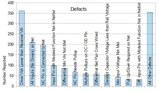
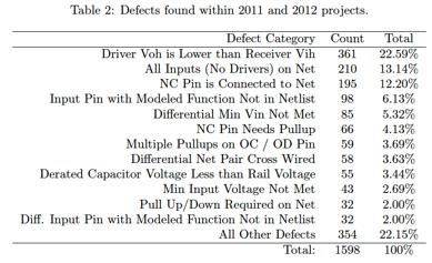
Ten years ago, the schematic design was very simple, and the error checking of the schematic did not seem to require too much manpower. However, more than 10 years later, our design has become increasingly complex. When a design contains multiple multi-pin devices and circuits for large circuit board connectors, there are a number of risks that may be brought into the manufacturing process. In this regard, we all know the consequences - rework. Recently, I had a long conversation with AlTIum about the new technology related to Valydate's schematic integrity analysis. In the past few years, designers have made mistakes in the schematic design process and have benefited us a lot. This will be of great benefit to us and to the designers, because it allows us to understand how many potential errors occur in the schematic design process and how many of these errors can actually be found through manual inspection. Valydate has an interesting history. We originally wanted to develop an EDA tool for schematic integrity analysis, and there was not enough investment at that time. How can this be solved? So we started from a small place, through the provision of services to enhance technology, through the customer's real project assessment for technology promotion. Is this effective? The answer is yes. We obtained reports from our customers and found similar mistakes that the designers made during the schematic inspection process. Some of these may be what you have committed. Valydate has run validation reports for hundreds of schematics for two years between 2011 and 2012. We divide the survey results into two categories: Critical mistake. This includes errors that appear in the schematic and, if left untreated, are likely to affect the design. Design flaws. Although not as critical as a critical error, it is very likely to result in the loss of component functionality. We were very surprised at the types of key design errors found during the schematic inspection. Up to 21% of critical design errors are related to power loss, and 18% are related to multiple outputs of a single point network. Did you make these mistakes in the design process? The design flaw itself also reflects some interesting phenomena, and the potential design flaws are far more than the key errors. What are the most common? The driver voh accounts for 22% less than the receiver vih. Are you familiar with these situations? What I find most appealing is that at the end of our two-year study, we identified commonalities between design errors. This is different from the one-off mistakes that designers make. There are hundreds of different schematics for this study. They all share the same design flaws. I don't think this is a designer's fault. Schematic design review contains too many aspects. Every time you publish, mistakes follow. In general, there are too many human factors involved in the schematic review process. How do you know what caused the design defect? After summing up the results of the two years of research, we have discovered a common trend of common design errors - they all involve power networks, programmable devices, and improper pull-up/pull-down resistors. In addition to the schematic analysis tools, we summarize the practical skills that designers must keep in mind when designing eight designs. We hope that everyone can avoid some or all of the design errors in this area. When designing the schematic, make sure that each required board voltage has a defined power network and keeps the network name consistent. If the network name is not exactly the same, an incorrect connection may be made. Be sure to check the power pins of each active device to ensure that the connected power supply has the correct minimum and maximum voltages. Make a list of grounded networks on the schematic to ensure that each grounded network has a specific ground source. Develop the following conventions: Verify that each schematic symbol that uses the component includes a label for manual review during the schematic design phase, and that the same pin definitions as in the device data sheet are used and used. If you are using a programmable device in your design, make sure that your circuit board netlist is connected to the device and the pin definitions are accurate. Verify that the programmable pin definitions do not conflict with the definition needed for the board. Mixing pin configurations can cause errors, especially when an FPGA defined as an output is defined as an input. During the design process, communicate with the FPGA team as early as possible, and agree on the pin name, direction, technology, pull-up/pull-down impedance, and power supply voltage. Verify all open-drain networks in your design to ensure that they have at least one pull-up/pull-down resistor. Finally, it comes down to how much time you are willing to invest in schematic review. More than a decade ago, manual review was sufficient. However, the current schematic is too complex and we cannot fully verify it manually. What we really need is a set of schematic integrity analysis tools that can run all the reviews, freeing up time for more pressing tasks. Valydate is conquering this problem. A few weeks later, we are happy to work with AlTIum Designer to launch another new extension application that will automate the schematic review process for you. Let us stay tuned! Michael is an outstanding business leader who has continuously promoted the establishment of customer and employee loyalty over the years, continues to bring ever-increasing profits and market share to the company, and guides the global R&D team. Prior to Valydate, Michael held management positions at companies such as Nortel Networks, CoreSim, and Fidus Systems, including business development, sales, operations, and engineering. It was under his leadership that Fidus Systems was able to enter the Silicon Valley. At present, Michael is the CEO of Valydate, which was founded in 2010 by him. Michael holds a bachelor's degree in computer systems engineering from Carleton University and a master's degree in business administration from the University of Ottawa. He enjoys numerous honors and awards and is the winner of the OBJ 2009 Forty under Forty Award.
What`s your impression for Intel I3 Laptop? You can take i3 Laptop Deals as the entry level of Gaming Laptop . There are different parameters standards,like 14 Inch Laptop I3 11th Generation, 14inch 256GB Intel I5 11th Generation Laptop, 14.1 inch Intel i7 11th Generation Laptop, 15.6 inch I3 10th Generation Laptop,15 inch Intel I5 10th Generation Laptop, 15inch Intel i7 11th Generation Laptop, etc. That`s some of Top 10 Gaming Laptops. To operating OS, more than 80% clients choose windows 10, home or pro option; nowadays windows 11 is new arrival, you can choose as your demand. Rich slots meet your different potential application scenarios, home, office, public places, academic situations, etc.
Dual storage channels, support HDD and SSD. Your customers can update in future according potential demands.
Of course, other type, like yoga notebook, 2 In 1 Laptop , Android Tablet, Custom All In One PC , 14 inch Student Laptop, i7 16gb ram 4gb graphics laptop, etc. available here also. Just call us and get right details quickly.
Intel I3 Laptop,Laptop I3 11th Generation,i3 10th Generation Laptop,i3 Laptop Deals,Laptop Intel Core I3 Gen 11 Henan Shuyi Electronics Co., Ltd. , https://www.shuyielectronics.com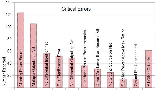

Ten years of difference