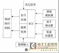
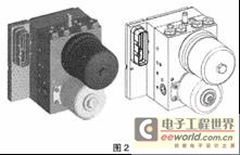
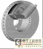
The end of hydraulic braking-an introduction to electronic brake (EMB) technology development As consumers pay more and more attention to vehicle safety, vehicle braking systems have undergone several changes and improvements. From the initial leather friction brakes, to the emergence of drum and disc brakes, and then to the emergence of mechanical ABS braking systems, followed by the development of electronic technology, there were analog electronic ABS braking systems and digital electronic control. ABS braking system, etc. In the past 10 years, western developed countries have launched research on vehicle wire control systems (x-by-wire), and wire-controlled brake systems (brake-by-wire) have emerged at the historic moment. As a result, they have launched electromechanical brakes. ) Research, in simple terms, the electromechanical brake is to change the part that was originally driven by hydraulic or compressed air to be driven by an electric motor, in order to improve the response speed and increase the braking efficiency, etc., while also greatly simplifying the structure and reducing the assembly And the difficulty of maintenance. Due to the continuous improvement of people's requirements for braking performance, after adding a large number of electronic control systems such as ABS, TCS, ESP, etc. to the traditional hydraulic or air brake system, the structure and piping layout are more complicated, and the hydraulic (air) circuit The hidden danger of leakage has also increased, and the difficulty of assembly and maintenance has also increased. Therefore, the electromechanical brake system with relatively simple structure and reliable function integration is more and more popular. It is foreseeable that EMB will eventually replace the traditional hydraulic (air) brake and become the future development direction of vehicles. 1 Introduction to the development of brake-by-wire Brake-by-wire refers to the integration of a series of intelligent brake control systems. It provides the functions of existing brake systems such as ABS, vehicle stability control, power-assisted braking, traction control, etc. The system is organically combined into a complete functional system. The original brake pedal is replaced by a simulation generator to accept the driver's braking intention, generate and transmit the brake signal to the control and actuator, and simulate the feedback to the driver according to a certain algorithm. Obviously, it requires a very safe and reliable structure for normal work. Its working principle is shown in Figure 1: Due to the limitation of technological development, there are two types of brake-by-wire systems: 1.1 Introduction to EHB EHB (Electro-Hydraulic Brake) is a wire-controlled hydraulic brake, which is developed on the basis of traditional hydraulic brake. EHB replaces the pressure regulator and ABS module in the traditional brake with an integrated brake module. This integrated brake module contains motors, pumps, batteries, etc. It can generate and store brake pressure, and Separately adjust the braking torque of the four tires. Compared with traditional hydraulic brakes, EHB has made significant progress. Its compact structure, improved braking performance, convenient control and reliable brake noise are significantly reduced, no vacuum device is required, and the brake pedal kick is effectively reduced. Good pedal feel. Due to the improvement of the degree of modularity, in the vehicle design process, the design flexibility is increased, the number of parts of the brake system is reduced, and the layout and space of the brake system in the vehicle are saved. It can be seen that EHB has been greatly improved compared to traditional hydraulic brakes. However, EHB still has its limitations, that is, the entire system still requires hydraulic components, and its basic is still inseparable from brake fluid. The emergence of EHB is mainly to lay the foundation for future research and production of EMB, and to accumulate a lot of production experience. As early as 1993, FORD had an electric car that used EHB. Later, General Motors also used an EHB brake system on one of its cars. It can be seen that foreign major automobile companies have already started research on brake-by-wire braking systems. The following figure shows the structure diagram of an EHB developed by DELPHI: 1.2 Introduction to EMB If EHB is called a "wet" brake-by-wire brake system, then EMB is a "dry" brake-by-wire brake system. EMB is the English abbreviation for Electromechanical Brake. The biggest difference between it and EHB and HB is that it no longer requires brake fluid and hydraulic components. The braking torque is completely generated by the motor-driven actuator installed on the four tires. Therefore, the corresponding elimination of the brake master cylinder, hydraulic lines, etc. can greatly simplify the structure of the brake system, facilitate layout, assembly and maintenance, and more significantly, with the cancellation of brake fluid, the pollution of the environment is greatly Reduced. In addition, since many existing components can be eliminated accordingly, the weight of the system can be greatly reduced, and it is convenient for comprehensive active control of the vehicle chassis. Its outstanding advantages are: no brake piping is required to reduce the manufacturing cost and the difficulty of installation and layout, brake performance has been improved, performance is stable, no need for brake fluid reduces costs and environmental protection, easy to integrate into the vehicle In the control network (CAN bus), due to the reduction of the number of components and the occupation of space, because the brake pedal only provides a reference, the input does not directly affect the brake system to improve the performance of the pedal. Since the 1990s in the 20th century, some well-known manufacturers of automotive electronic parts such as Bosch, Siemens and ConTInentalTeves have successively started research on EMB electric brakes, and have done some corresponding system simulation and loading tests. The following figure shows the schematic diagram of the EMB braking system developed by a German company: 2 EMB electronic mechanical brake system 2.1 Development and status of EMB EMB was first used in aircraft. For example, the F-15 fighter in the United States used EMB brakes, but it was slowly transformed into cars. EMB is very different from traditional braking systems, and its execution and control mechanisms need to be completely redesigned. The actuator needs to be able to smoothly convert the rotation of the motor into the translation of the brake shoe, need to be able to decelerate and increase torque, need to be able to automatically compensate for the brake gap caused by long-term work, etc., and its structure must also be limited due to the volume. Ingenious and compact, it is a very important part of the entire EMB system; its control part also requires precise control of the motor speed and rotation angle to prevent brake lock. In recent years, some large international auto parts manufacturers and auto factories have conducted some research work on EMB braking systems, and have also applied for some patents. The main companies participating in the competition are: ConTI-nental Teves, Siemens, Bosch, Eaton, Allied Signal, Delphi, Varity Lucas, Hayes and so on, but the domestic research on this project is basically blank, only the Second Automobile, Tsinghua University and Nanjing University of Aeronautics and Astronautics have carried out some related research work. 2.2 Structure and classification of EMB system For the mechanical actuator of the EMB system, it directly receives the torque generated by the motor and amplifies the effect on the brake disc. Its structure should meet the following basic requirements: 1) Compact structure, easy to arrange; 2) Ability to transform rotation into translation; 3) There are deceleration torque increasing and self-increasing mechanism; 4) Ability to automatically compensate for braking clearance; 5) Provide parking brake when parking; 6) Safe and reliable, long working time. As mentioned above, each company has achieved its own research results and successfully applied for some patent protection. In general, the EMB brake system can be divided into two categories from the perspective of energy saving. One is that the electric motor directly drives the mechanical actuator and then acts on the brake disc. It is typically a brake developed by ConTInental Teves. The second type is that the motor acts on the brake disc indirectly through a self-energizing mechanism, which can greatly reduce the energy consumed by the system. German Aerospace Center (DLR) internal data shows that the EMB brake system eBrake developed by its company is better than the first. One type of structure saves about 83% of energy. The first structure of the brake is characterized by simple control and stable braking process; however, because the motor provides all the thrust required to push the brake pads, the power required to drive the motor is very large, resulting in the size, weight and Energy consumption is relatively large. The second structure of the brake indirectly uses the kinetic energy of the car as a self-energizing brake, and the power required by the drive motor can be greatly reduced. Only about 3% of the energy consumption of other alternatives is required. It must be smaller than the first type of brake, but at present this type of brake is difficult to control and the brake stability is not as good as the former. 2.3 Problems to be solved by EMB The EMB braking system has obvious advantages that many traditional braking systems cannot match, but due to its short development time, there are also many problems that need to be solved: 1) If the system circuit is broken or the Power Supply fails, how should the brake system act? What should I do if the brake pedal simulator malfunctions? Therefore, research on system reliability and accident insurance needs to be strengthened. 2) Since a large amount of heat is generated during high-speed braking, it is necessary to strengthen the thermal stability and heat dissipation performance of the system. Repeated experiments are needed to verify the performance and stability of the drive motor and other components under high temperature conditions. 3) The electric brake system uses a lot of electric control technology, it is difficult to avoid a large number of electronic circuits, and because the vehicle is complicated and works in the externally exposed electromagnetic field and the earth's magnetic field environment, this requires strengthening the resistance of the electric brake system Interference ability. 4) The action of driving the motor consumes a lot of electrical energy. This is a test of the 12v power supply currently used by vehicles. In the future, a voltage of 42V will be used to provide energy to the system. 5) At present, the vehicle EMB braking system should be strengthened to integrate with other current vehicle electronic control systems. It is best to form an integrated and modular chassis control system to comprehensively control the vehicle. 6) Due to the use of a large number of sensors, control chips and new technologies, the cost of the current electric brake system is higher than the cost of the existing hydraulic brake system, so reducing the cost of the system is also a problem that needs to be solved. 2.4 Research direction of EMB At present, the technology of EMB brake system is not mature, and there are still many technical problems that need to be solved. Foreign countries focus on the research of electric brake systems in the following aspects: 1) High temperature resistant electronic components; 2) Mechanical-electronic actuators; 3) Adaptively adjustable control algorithm; 4) Highly sensitive and inexpensive sensors; 5) System fault tolerance control; 6) High-reliability wires and connectors; 7) Design of torque motor. The research on high temperature resistant electronic components mainly involves two aspects: one is to work hard on the electronic components themselves to improve their ability to withstand high temperature and work stability at high temperature; the other is to improve the material of the brake disc And improve its heat dissipation. Provide a good environment for the work of electronic components. Scholars at home and abroad have also done a lot of work on the research of brake control algorithms and advanced sensors. At present, there are mainly three kinds of vehicle brake control algorithms: sliding mode control algorithm, logic threshold control, optimal control algorithm, etc. In the fault tolerance of electronically controlled brake systems, there have been a lot of papers on this issue recently. Because this problem involves the safety and reliability of the brake system, it is a key and crucial research direction. Some scholars use experimental methods to detect and evaluate the response of EMB to braking requests, and use certain algorithms to ignore instantaneous error signals in order to achieve fault-tolerant control of the system; A central control chip (brake-by-wire Manager), which is a redundant design specifically for fault-tolerant control, and is equipped with specially written software for fault-tolerant control processing; the most recent is to introduce a monitor in the system ( monitor), used to detect signals that may cause system errors and failures, and then generate and error detection codes, according to the codes to deal with failures and improve safety. Obviously, the fault-tolerant control of the vehicle electronic control system is a relatively difficult problem involving many aspects such as computer hardware, software, communication protocols and so on. The design and manufacture of other connecting cables and sensors will be simpler. In addition, during the braking process, the motor will work in the harsh environment of "locked rotor", so the reliability of the motor is high, and the structure must be small and compact, easy to install, and can work reliably in various harsh environments. As for mechanical actuators, a considerable number of companies have come up with physical products. 3 Conclusion It can be seen from the above that although EMB brakes have unparalleled advantages and broad application prospects compared to traditional hydraulic brakes, they also have their own problems that need to be solved. More widely used. Constant Current Led Driver,Led Driver 12V,Led Driver 24V,Led Driver 30W Ninghai Yingjiao Electrical Co., Ltd. , https://www.yingjiaoadapter.com