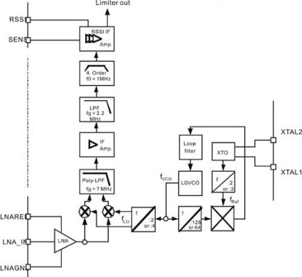
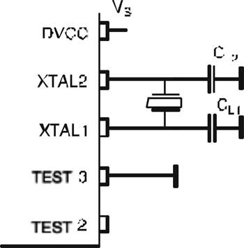
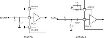
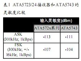
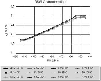
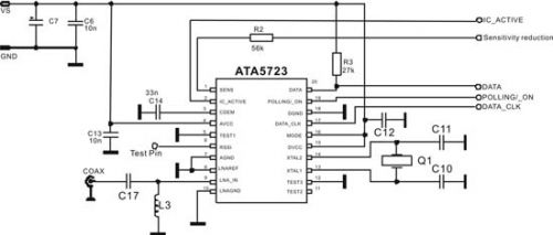
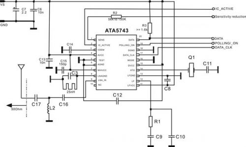
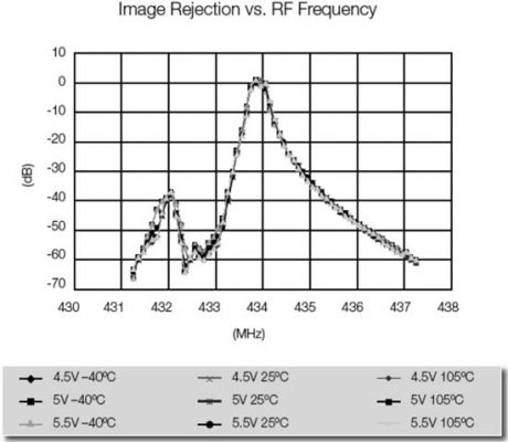
Atmel Corporation's receiver series ATA5723, ATA5724 and ATA5728 not only inherit the advantages of its well-known UHF remote control receiver chip ATA5743, but also have its own characteristics. The ATA572x series is available in three models for the Industrial, Scientific, and Medical (ISM) band, with the ATA5723 band ranging from 313 to 317 MHz; the ATA5724 from 432 to 436 MHz; and the ATA5728 to 868 to 870 MHz. The RF front end of these devices is manufactured using Atmel's RF BiCMOS (UHF6) process and in a small SSO20 package, making them ideal for automotive electronics applications where space is at a premium, such as remote keyless entry systems (RKE) and Tire Pressure Monitoring System (TPMS). The pin-to-pin compatibility of these three devices allows system designers to develop a line layout that can be applied to different solutions around the world. This article refers to the address: http:// Figure 1 Typical automotive RF application Figure 1 shows the RKE and stopper automotive electronics applications supported by the Atmel receiver chip. The figure shows the exchange of information between the car and the key fob. If the driver presses the key fob button to open the door, the microcontroller will transmit the authorization data to the UHF transmitter, which will send the data out. If the data is received, the receiver will pass the data to the microcontroller in the car control unit for verification. If the data sent by the key card matches the authorization data of the car, the door will open. The engine application flow for starting the engine is similar. This article will focus on RF data transmission, especially on the receiver side. Similar to the ATA5743, the ATA572x series of receivers have a polling feature that puts the microcontroller in standby mode, which saves system current consumption. In receive mode, its operating current draw is approximately 8 mA. The ATA572x family of devices offers high levels of integration, including fully integrated intermediate frequency (IF) filters, low phase noise VCOs, PLLs, and loop filters for excellent reception performance. The ATA572x series (Figure 2) is based on a single-ended RF input and is ideal for 1/4-wavelength antennas or loop antennas implemented in printed circuits. This family of chips supports typical protocols required for general applications such as Manchester encoding and Bi-phase encoding. As will be seen in the discussion below, the ATA572x family requires only a few external components and does not require an external IF filter; typically only 10 passive components, one crystal and one RF antenna are required to create a receiver circuit application. In addition, the ATA572x family of receivers have a logarithmic RSSI output that determines the signal strength of different transmitters with high resolution. Figure 2 ATA572x series block diagram System specification The RF front end of the ATA572x family of receivers uses a low IF superheterodyne circuit to convert the input signal to an IF signal of approximately 1 MHz with an image rejection of 30 dB. The RF front end consists of a low noise amplifier (LNA), a local oscillator (LO), an I/Q mixer, a multiphase low pass filter, and an intermediate frequency amplifier. The signal from the LNA is downmixed into an intermediate frequency signal and filtered by a fully integrated filter circuit. The exact structure of the RF front end of the ATA572x series receiver is shown in Figure 2. The PLL in the circuit generates the frequency required by the mixer through a fully integrated synthesizer with a built-in low noise LC-VCO (Voltage Controlled Oscillator) and PLL loop filter. XTO (Crystal) produces the reference frequency fREF (fREF=fXTO/2 for 868 and 433 MHz devices, fREF=fXTO/3 for 315 MHz devices). XTO is a two-pin oscillator that operates at the voltage resonance frequency of a quartz crystal. Its oscillating signal is a high current, low voltage signal. Therefore, at the crystal frequency, the voltage on the chip pins XTAL1 and XTAL2 is small. As shown in Figure 3, the crystal should be grounded from XTAL1 and XTAL2 via two capacitors (CL1 and CL2). This special crystal structure has a negative resistance oscillation tolerance of 1,500 Ω. Therefore, the crystal oscillator is not demanding, which helps to avoid the “stop vibration†problem. Due to the large negative-resistance oscillation tolerance of the ATA572x series, a lower cost crystal can be selected. Figure 3 XTO external components The built-in LC-VCO generates fVCO, which is twice or four times the frequency of the mixer. The VCO frequency is divided by two or four to obtain the I/Q signal of the mixer (fLO=fVCO/2 for 868 MHz devices and fLO=fVCO/4 for 433 and 315 MHz devices). This VCO frequency is also divided by 128 or 64 and is also supplied to a phase frequency detector for comparison with fREF. Therefore, the output of the phase frequency detector is passed through an integrated loop filter and produces a control voltage for the VCO. Figure 4 ATA572x and ATA574 - Matching Impedance 50Ω The RF Receiver ATA572x family has the highest sensitivity when LNA power is matched. This makes it easy to match the SAW filter and the 1/4 wavelength antenna. Figure 4 shows an example of an application circuit with an ATA572x family of chips and an ATA5743 chip for matching impedances of 50Ω. In the ATA5743 application circuit, five passive components are required for optimum sensitivity. The circuit must use inductor L1, capacitor C1, and 100pF capacitors to achieve LNA input impedance matching. For optimum sensitivity, the inductance generated by the LNA's ground connection must be compensated by a voltage resonant circuit that resonates with C3. Inductor L3 establishes a DC channel to which the LNA is grounded. In contrast, the ATA572x family is simpler, and sensitivity can be optimized by simply connecting two passive components (L1 and C1) to the LNA input pin. Table 1 shows the sensitivity comparison between the ATA5723/24 receiver and the ATA5743. The sensitivity improvement achieved in the table is shown. The RSSI output with a dynamic range of 60 dB is another feature of the ATA572x family of receivers. The IF amplifier signal is boosted by the RSSI amplifier before entering the detector, and the signal can be taken out at the output pin. The RSSI output signal is used in applications to determine the signal strength of different transmitters at different locations or distances from the receiving antenna. Figure 5 shows the RSSI characteristic curve of the ATA572x series receiver, which is a linear graph of signal strength (dBm) and VRSSI. Figure 5: RSSI characteristic curve The sensitivity reduction feature is a proven feature of the Atmel receiver family. The output voltage of the RSSI amplifier is compared internally to a threshold voltage; this threshold voltage is determined by the value of the resistor (Rsens) at the SENS pin. This resistor must be connected to a power supply (VS) or to ground. The output of the comparator is fed into the digital control logic, which determines whether the receiver is operating in a low sensitivity state or in the highest sensitivity state. Grounding the Rsens, the receiver processes the signal at the highest sensitivity, connecting to Vtt, and the receiver reduces sensitivity. In practical applications, this function can be used to define two different receiving distances for RKE applications. Figure 6 ATA5723 demo board circuit (matching impedance 50Ω) Figure 7 ATA5743 demo board circuit (315 MHz device with matching impedance of 50Ω) Figures 6 and 7 show Atmel's demo board circuit developed for the ATA5723 and ATA5743. In comparison, it is clear that the ATA5723 requires far fewer external components, only 12, while the ATA5743 has 20. There are two reasons why the number of external components is reduced. First, the ATA572x family integrates loop filters compared to the ATA5743. Second, the LNA in the ATA572x family is directly grounded and does not require any compensation circuitry. The ATA5743 requires an LC circuit for optimum sensitivity. For some applications, it is sufficient to achieve image rejection of typically 30 dB. In this case, the front-end SAW filter is not required. For more demanding applications, a SAW filter is required to achieve the desired sensitivity. The reception frequency response characteristics without the SAW filter are shown in Fig. 8. Figure 8 narrowband receive frequency response Conclusion The ATA572x family of receivers not only inherits the advantages of the ATA5743, such as integrated IF filters, self-polling, bidirectional data interfaces, reduced sensitivity requirements, ASK, FSK, DATA_CLK, and digital noise suppression, but also adds some features. Features such as logarithmic RSSI output, high integration, and more convenient RF matching. These features combine to make it a flexible receiver for RKE and TPMS automotive electronics applications.
Solar energy system, off gird pv system, grid pv system, solar power system, Solar Panel system, on grid solar system, grid tied solar system,20kw solar system
Solar energy system include Solar photovoltaic system: 1. Off grid photovoltaic system mainly consists of solar modules, controllers, and batteries. To supply power to AC loads, it is also necessary to configure an AC inverter. 2. Grid connected photovoltaic power generation system. 3. Distributed photovoltaic power generation system. Distributed power generation or distributed energy supply.
Solar Engergy System,Gird Solar Power System,Pv System For Carport,Energy System Off Grid Solar System PLIER(Suzhou) Photovoltaic Technology Co., Ltd. , https://www.pliersolar.com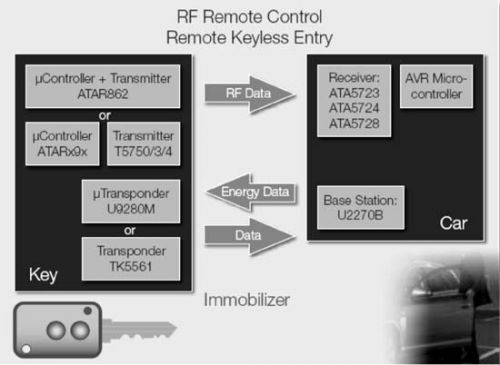
solar cell type
mono crystalline, half cut cell
solar energy pv system include
on grid system, off grid system, hybrid system
solar configuration
solar panel, inverter, battery, bracket cabels, mc4 connector
Product details and pic

