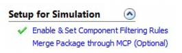
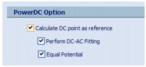
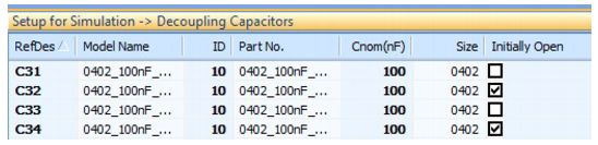
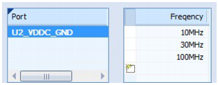
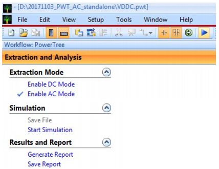
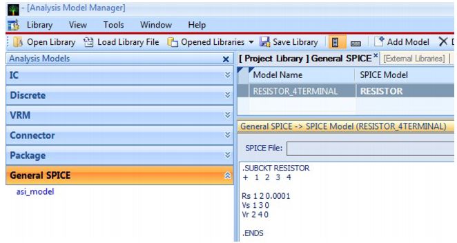
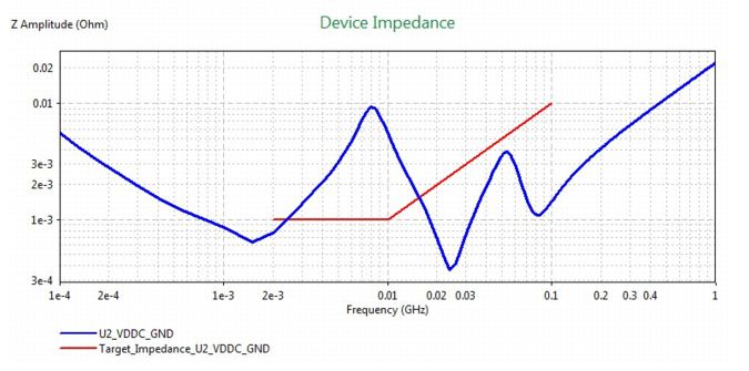
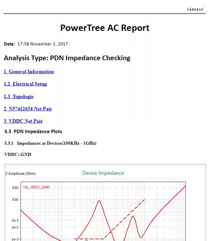
OptimizePI This section describes new features in the Cadence® SigrityTM 2017 OptimizePITM QIR2 release. Post-Layout Optimization Flow Supports MCP Package Model Sigrity's MCP (Model Connection Protocol) is a text header that is written into the model generated by the Sigrity tool. It allows automatic connection between the model and the physical layout. The "merge encapsulation by MCP protocol" step has been added to the Post-Layout analysis workflow (decoupling capacitor optimization), which allows Post-Layout analysis and PDN impedance inspection workflows to maintain consistency and portability through the Switch Workflow feature. Support frequency sweep, starting from 0 Hz For a typical decoupling capacitor optimization, it is not necessary to simulate to a very low frequency, because the Bulk decoupling capacitor dominates the response. However, many users want to use OptimizePI to extract the broadband model of their PDN. This new version allows 0 Hz as the starting frequency and is the recommended best practice setting. Note that there are other advanced options for low-frequency precision modeling (PowerDC DC point calculations, equal potential options and performing DC-AC fitting options). These options lock the start frequency to 0Hz. Capacitor position open circuit support in PDN impedance check flow For various reasons, some designs of decoupling capacitor components may or may not be placed in the manufacturing process. In this release, the ability to designate the decoupling capacitor as the initial open circuit (not placed) in the PDN Impedance Check workflow has been added. This function was previously performed in the post-layout analysis (decoupling capacitor optimization) workflow. From this version, the two workflows become more consistent and portable. Unload the impedance curve from the result viewer This release adds the ability to manually load the impedance curve after unloading the simulation. This provides more flexibility for analysis and comparison of simulation results. You can access this feature by right-clicking in the 2D Results window and selecting the option from the shortcut menu. Custom frequency setting in HTML report for target impedance check The target impedance check is an excellent indicator of the PDN performance pass/fail. In addition to the continuous curve checks that have been performed, OptimizePI also adds the ability to report impedance results at specific frequency points. These frequency points are defined in the HTML Report Options window as shown below. The generated HTML report contains a table of results, as shown below. OptimizePI and PowerTree This section highlights PowerTree improvements related to AC emulation and OptimizePI integration. For more new features of PowerTree QIR2, see the PowerTree section. AC Simulation Support in Stand-Alone PowerTree Utilities In this release, stand-alone PowerTree applications implement Sigrity-style workflows with independent DC and AC modes. AC mode has the ability to run the AC simulation of the PowerTree schematic directly from the PowerTree application. OptimizePI AC emulation runs in the background with the TCL command. Note: Licenses for the OptimizePI or Allegro PI options are required to run AC schematic emulation in a PowerTree application. AMM Universal Spice Model for Resistors and Inductors in PowerTree The multi-terminal AMM generic SPICE R and L models can now be applied in PowerTree. Target Impedance Support in PowerTree AC Schematic Simulation New in this release is the ability to display the target impedance constraints covered in the AC schematic simulation results. This feature is very useful to circuit designers and can be used to determine if additional and/or different capacitors are needed. HTML Report of PowerTree AC Schematic Simulation Results This release adds the ability to generate HTML reports for AC schematic simulation results. Create a report by clicking on the steps in the workflow. The following figure shows an excerpt from an actual report.
Draw-wire sensors of the wire sensor series measure with high linearity across the entire measuring range and are used for distance and position measurements of 100mm up to 20,000mm. Draw-wire sensors from LANDER are ideal for integration and subsequent assembly in serial OEM applications, e.g., in medical devices, lifts, conveyors and automotive engineering.
Linear Encoder,Digital Linear Encoder,Draw Wire Sensor,1500Mm Linear Encoder Jilin Lander Intelligent Technology Co., Ltd , https://www.jllandertech.com