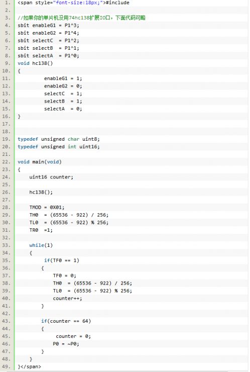
The use of the microcontroller timer can be said to be very simple, as long as you master the principle and have a little C language foundation. The main points are as follows: 1. You must know the original form of the English abbreviation so that you don't need to remember the name of the register. Understanding is the best way to remember. A good textbook will definitely give the original form of all English abbreviations. 2. Try to use the image method to remember. For example, the functions on each of the two registers, TCON and TMOD, usually have a chart in the tutorial, and you will keep recalling the image of that chart as you study. 3. TMOD: Timer/Counter Mode Control Register (TIMER/COUNTER MODE CONTROL REGISTER) The timer/counter mode control register TMOD is an 8-bit register defined bit by bit, but only byte addressing can be used, and its byte address is 89H. The format is: the low four bits define timer/counter C/T0, the high four bits define timer/counter C/T1, the description of each bit: (1) GATE——Gate control. When GATE=1, the timers T0 and T1 are started by the external interrupt pins INT0 and INT1. When the INT0 pin is high, TR0 is set to start the timer T0; When the INT1 pin is high, TR1 is set to start the timer T1. When GATE=0, only TR0 and TR1 are set to start timers T0 and T1 respectively. (2) C/T-function selection bit When C/T=0, it is timing function, when C/T=1, it is counting function. The counting function is selected when set, and the timing function is selected when clearing. (3) M0, M1-mode selection function Since there are 2 digits, there are 4 ways of working: M1M0 working mode counter mode TMOD (set timer mode) 0 0 Mode 0 13-bit counter TMOD=0x00 0 1 Mode 1 16-bit counter TMOD=0x01 1 0 Method 2 Automatically reload 8-bit counter TMOD=0x02 1 1 Method 3 T0 is divided into two 8-bit independent counters, T1 is an 8-bit counter without interruption, TMOD=0x03 MCU timer 0 is set to work mode 1 is TMOD=0x01 Here we must know that T in TMOD means TIMER/COUNTER, and MOD means MODE. As for the function of each person, you only need to remember the diagram and know the prototype of each English abbreviation. When using TMOD in the program, immediately recall the diagram and figure out the meaning of each word according to the original form of the abbreviated word. If the meaning is not very clear, check the manual. After several times, the TMOD diagram is already in your mind. . The 8-bit GATE bit itself means a gate. 7-bit C/T Counter/Timer 6-bit M1 Mode 1 5-bit M0 Mode 0 4. TCON: Timer/Counter Control Register (TIMER/COUNTER CONTROL REGISTER) TMOD is divided into 2 sections, and TCON control is more refined, divided into four sections. Only the upper four sections are used in this article. TF0 (TF1)——Counting overflow flag bit, when the counter overflows, this bit is set to 1. (1) TR0 (TR1)-timer operation control bit When TR0(TR1)=0, stop the timer/counter When TR0(TR1)=1, start timer/counter work (2) IE0 (IE1)-external interrupt request flag When the CPU samples P3.2 (P3.3) to have a valid interrupt request, this bit is set by hardware. After the interrupt response is completed, it will be automatically cleared by hardware when it turns to interrupt service. (3) IT0 (IT1)-external interrupt request signal mode control bit When IT0 (IT1) = 1 pulse mode (the trailing edge negative jump is valid) When IT0 (IT1) = 0, level mode (active low), this bit is set or cleared by software. (4) TF0 (TF1)-counting overflow flag When the counter overflows, this bit is set by hardware. When switching to interrupt service, it will be automatically cleared by hardware. There are two situations in the use of the flag bit for counting overflow: when the interrupt mode is used, it is used as an interrupt request flag bit; when the query mode is used, it is used as a query status bit. Pay attention to the memory method and understand the original form of the word, so you will never confuse TF and TR. The F of TF is the F that overflows Over Flow. The R of TR is to run Run. The default is 0 to not run, of course, it must be set to 1 to run. 5. Calculation of the delay time of STC MCU STC89C52RC timer The delay time should be calculated according to the crystal frequency, which may be different for different boards. Clock cycle: 1/Clock source, the crystal oscillator frequency is 11.0592M, then the clock period is 1/11059200 second Machine cycle: Generally, 51 single-chip microcomputers have 12 clock cycles, which is 12/11059200 seconds Maximum time for a single timing: If it is a 16-bit counter, the maximum value of 16-bit is 65535, which can count 65536 times in total. The basic constant must be remembered, and the maximum value of 8 bits is 255, which can count 256 times in total, and the value represented by each of the 8 bits must be remembered. 12 * 65536/11059200 = 0.0711 s, that is, the timing within 71 ms can be completed in a single timing. If the timing time exceeds 71 ​​ms, it will loop. A timing requires several machine cycles: Calculation formula: timing seconds/machine cycle For example, if you want to time for 1 second, 1/(12/11059200)= 921600 times, the 16-bit counter can count up to 65536 times, 921600 times have already benefited. We can time 10 ms each time, and cycle 100 times to time 1 second. If 1 s is reduced by 100 times, it is 10 ms, that is, 9216 times are counted each time. Indeed the initial value of the counter: When the timing is 10 ms, if the counter starts counting from 0, it is not known when 9216 times are reached. So it should count 9216 times. The 16-bit counter counts up to 95536 times, and then overflows. When it overflows, the TF bit of TCON will be set to 1. As long as the TF bit is checked frequently, you can know when the 10ms timing is completed. Calculation formula: counter initial value = maximum number of counts-number of counts required If the timing is 10 ms, the initial value of the counter is 65536-9216 Calculate the high and low bits of the counter: The 16-bit counter is composed of two 8-bits, and the maximum count of 8-bits is 256. and so: Counter high bit = initial value/256 Counter low = initial value %6 6. STC89C52RC microcontroller timer sample code: M5 Circular Connectors,M5 Waterproof Circular Connector,M5 Waterproof 4P Male Connector,M5 Male Head Waterproof Connector Shenzhen HuaTao Electronic Co., LTD , https://www.htconnector.com