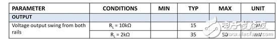
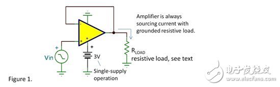
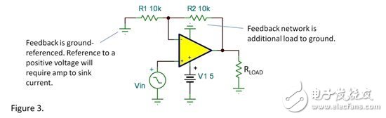
Rail-to-rail amplifiers produce an output voltage that is very close to ground...but how close is it? We are talking about CMOS operational amplifiers. It is often used in low voltage designs when you are working hard to maximize output voltage swing. The specifications for these devices are usually as follows: This makes it look like the output is never closer to ground than 15mV, and the last 15mV is critical for accurate zero measurements. But please wait... you really need to understand all the states of this specification. Assume that the load is "half" connected between the two power terminals. We usually see these states at the top of the spec sheet, and you will see a statement like this... RL is connected to VS/2. In this specification state, the amplifier must draw current through the load resistor when the output is close to ground. It reflects the method of amplifier testing, which ensures that it can properly output and sink current. This is a sensible, conservative way to test and specify amplifiers, but it is not the way to connect your load. Suppose your load is connected to ground as shown in Figure 1. The load resistor actually helps pull down the output to ground, and the sinking current does not require an amplifier. In this state, most CMOS op amps can swing very close to ground—less than 1 to 2 millivolts. Specifications may not focus on this capability, but it is shown in the figure. Figure 2 shows that the output voltage swing is related to the output current. This figure may benefit from high precision, but you will see that the output voltage intersects the specific voltage rail when performing this test, ie ±2.75V. When operating from a single supply, the V- supply is equal to 0V. Now, I need to add some additional conditions. Note that in Figure 3, the feedback network is referenced to ground. You need to consider all the sources of the amplifier load, not just RL. In this case, R1 + R2 is an effective additional ground reference load in parallel with RL. However, if R1 refers to a positive voltage, an amplifier is required to draw current from the feedback network when the output is close to 0V, and the output swing cannot be very close to ground. Another additional condition. In the same circuit, if the gain is increased, the input bias voltage may make your output swing smaller. For example, when G=20, if the input is the bias voltage of the +1mV op amp, the zero input will produce a 20mV output. This is not due to the output swing limit, but the bias voltage problem. Of course, a small negative input voltage can bring an output that is very close to 0V, but your circuit will never have a negative input voltage. Again - the reactive load AC signal may be an exception. The load current and voltage are out of phase with the reactive load, so the amplifier may be required to draw current when the output voltage is close to ground. Finally - we are talking about CMOS operational amplifiers. Bipolar (BJT) op amp swings cannot be so close to ground. Low-voltage, battery-powered circuits are challenging because we seem to be always trying to maximize voltage swings. With a good understanding of the performance of the op amp, you can squeeze out more output swings to get close to ground. Fan Control Board Pcba,Engineering Control Board Pcba,Control Board Pcba Assembly ,Control Pcba Assembly Full Industrial CO.,ltd. , https://www.iotaindustrial.com