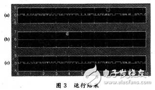
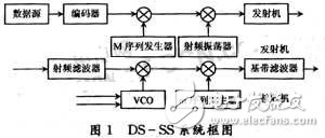
With the rapid development of communication technology, the advantages of spread spectrum communication technology have become more and more obvious and accepted, and have been widely used in various fields. At the same time, with the development and application of computer technology and simulation technology, how to apply some convenient and friendly software to simulate the communication system and simulate and analyze the simulation results has become an urgent technical requirement for communication workers. . In this paper, through the theory of spread spectrum technology and the description of the structure and working principle of the direct spread spectrum system, a simple direct spread spectrum communication system is simulated by Matlab and Simulink toolbox and other related toolboxes, and given the simulation conditions. It provides a reference for the relevant staff to carry out simulation of similar communication systems. A spread spectrum communication system refers to a communication system in which a spectrum of information to be transmitted is spread by a specific spreading function to become a broadband signal, transmitted to a channel for transmission, and compressed by a corresponding means to obtain a transmission information. The spread spectrum system must satisfy the following two criteria: the transmission bandwidth is much larger than the bandwidth of the original information transmitted; the transmission bandwidth is mainly determined by the spreading function, which is commonly used as a pseudo-random coded signal. (1) The theoretical basis of spread spectrum technology can be used by the Shannon (CEShannon) channel capacity formula: To describe. The formula shows that when the signal-to-noise power ratio of the transmission system decreases in the Gaussian channel, the system transmission bandwidth W can be increased to keep the channel capacity C constant. For any given signal to noise power ratio, the transmission bandwidth can be increased to achieve a lower information error rate. Spread spectrum technology is also applied to this principle, using high-rate spreading codes to achieve the purpose of extending the bandwidth of digital information to be transmitted. (2) Shannon pointed out that under the interference of Gaussian noise, the best signal for effective and reliable communication on the channel with limited average power is the signal with statistical characteristics of white noise. Gaussian white noise signals have ideal autocorrelation properties, but there are many technical difficulties in generation, processing, and replication. The statistical properties of some pseudo-noise sequences that are easy to generate and easy to process and control are close to the statistical characteristics of Gaussian white noise. Therefore, the spread spectrum communication system that uses the pseudo-random code to spread the spectrum of the baseband signal to be transmitted is superior to the conventional communication system. (3) Kharkevich theoretically proves that to overcome the influence of multipath fading interference, the best signal form transmitted in the channel should also be a signal form with statistical characteristics of white noise. Since the pseudo code in spread spectrum communication approximates the statistical characteristics of white noise, spread spectrum communication has the ability to resist multipath interference. 1.2 Classification of spread spectrum communication systems Spread spectrum communication systems can generally be divided into the following types according to their working methods: (1) Direct Sequence Spread Spectrum System (DS-SS): After multiplying the information signal to be transmitted and the high-rate pseudo-random code waveform, it directly controls a certain parameter of the RF signal and extends the transmission bandwidth. (2) Frequency hopping spread spectrum system (FH-SS): After the digital information is added to the binary pseudo code sequence modulo two, the output frequency of the RF carrier oscillator is discretely controlled so that the frequency of the transmitted signal varies with the pseudo code. Jump. (3) Time-hopping spread spectrum system (TH-SS): The time-out is the time and duration of the signal transmission and start-up using a pseudo-code sequence. (4) Hybrid: Two or more of the above three basic spreading methods are combined. The DS-SS system block diagram is shown in Figure 1. Assumption: Binary direct sequence spread spectrum, BPSK modulation. The BPSK modulated signal is expressed as: Suppose A=1, φ0(t)=0. The digital signal of the data source {an} is represented by d(u, t), c(u, t) represents the spread code waveform, and d(u, t) and c(u, t) are both binary waveforms. Therefore the expression of the output signal s(u,t) of the transmitting system is: d(u,t) is independent of c(u,t). s(u,t) is radiated into the space via the antenna and is contaminated by various signals and interference noise during the propagation. After the signal enters the receiver and undergoes a transformation opposite to the transmitting end, the information transmitted by the transmitting end can be recovered. In the spread spectrum receiver, this inverse transform is despreading and demodulating. Generally use relevant despreading, using: In fact c(u,t) is a real function, so c*(u,t)=c(u,t). Usually, carrier demodulation uses coherent demodulation. The two multipliers in the receiving system are related despreading and demodulating. The local spreading code is synchronized with the transmitting end, and the control tracking amount provided by the delay locked loop is used as the synchronization of the random delay of the channel. track. The signal output by the local RF voltage controlled oscillator is also tracked by the synchronous tracking amount provided by the phase-locked loop. If the correlator in the receiving system is ideal (and the second harmonic can be filtered out) and both the RF filter and the baseband filter are linear, the overall system model is also linear, from the receiver input to the baseband output. The entire process is linear. It can be assumed that other interferences and noises are zero. After calculation by integral transformation, etc., the useful signals output by the baseband filter are: It can be seen that as long as the baseband filter transmits the digital information d[u,t-τ(u)] without distortion, after processing by the baseband digital detector, the information {an) transmitted from the source of the transmitting end can be recovered. The function of the spread spectrum receiver to extract the useful signal is accomplished by fully utilizing the sharp autocorrelation property of the pseudo random code. The various interfering signals are not related to the local pseudo-code, and their energy is spread throughout the spread spectrum during processing, so the output through the baseband filter is small. The Simulink toolbox is special in Matlab's various toolboxes. It is a complete simulation environment and graphical interface developed from the ground up. In this environment, the user can complete all the processes for the simulation of the block diagram system with the mouse or keyboard, and achieve the simulation goal more intuitively, quickly and accurately. Another advantage of the Simulink toolbox is that he does not give any new functions. As a block diagram-oriented simulation software, Simulink has the following features: (1) Replace the program with the drawing of the block diagram. (2) The establishment and operation of the simulation is intelligent. (3) Diversification of input and output signal sources. Toolboxes commonly used in communication system simulation models include Simulink-based module toolboxes in addition to Simulink. The most commonly used are Powersys module toolboxes, DSP Blocks module toolboxes, Fix-PointBlocks module toolboxes, and Comm module toolboxes. The Powersys module toolbox provides a variety of subsystem models for power transmission and dragging, including power supplies, components, motors, power electronics, measurements, connections, and more. Digital Block Processing (DSP Blocks) module toolbox, including source library, signal drain (terminal library), general DSP library, math function library, filter library, spectrum analysis library and demo library. The Fix-Point Blocks module toolbox is mainly used to analyze the effects of limited computer word length on processing signals, including fixed-point arithmetic operations, fixed-point logic operations, fixed-point transform operations, and fixed-point processing. The transfer of points and the connection of fixed points. The communication system (Comm) module toolbox mainly includes a source of signal source and signal terminal, a source code and source decoding library, an error correction coding and error correction decoding library, a modulation and demodulation library, a multiple access library, a transmission filter, and Receive filter library and channel library. An intuitive communication system model can be easily built using the Simulink toolbox and other toolboxes based on it. The first stage is to graphically draw and edit the structure; the second stage is to perform computational simulation. In the first stage, we must first establish the block diagram of the link library, find the required icons from various libraries and arrange them; then connect the ports of each link according to the block diagram; finally, set the link parameters. Pay attention to the signal source at the input of the system, and add the signal terminal (that is, the device that observes or records the signal, such as an oscilloscope, voltmeter or file) to the output that the user cares about. Such a communication system is determined, and then simulations can be performed to determine system performance indicators and program comparisons. A simple direct expansion system model using Simulink simulation is shown in Figure 2. Source: Generated using the Random Integer Generator, which generates a random binary random signal as a source for a spread spectrum communication system. Spreading and despreading: The PN sequence generator is used to generate a pseudo-random code multiplied by the source to perform spectrum spreading, and the sequence is multiplied by the demodulated signal at the receiving end to complete despreading. Polarity conversion: In order to spread the source and pseudo-random code, it must be changed from unipolar to bipolar. In order to facilitate the modulation, it needs to be transformed once again to become a unipolar signal. At the receiving end, in order to facilitate despreading After demodulation, it is necessary to convert from a unipolar signal to a bipolar signal, and in order to facilitate display, it is necessary to perform another polarity conversion, and then display the bipolar signal to a unipolar signal. Modulation and demodulation: BPSK modulation and coherent demodulation are used. It can be simulated directly using the BPSK Modulator Baseband module PSK DemodulatorBaseband module. It can also be multiplied by a Sine Wave-generated carrier and spread-spectrum signal, and then modulated by a Zero-Order Hold. At the same time, a Zero-OrderHold is used at the receiving end. Demodulation is then performed by multiplying the Sine Wave carrier with the same frequency amplitude phase as the transmitting end. Channel: The AWGN Channel module is used to simulate an additive white Gaussian white noise channel. The signal-to-noise ratio (Es/No) of the channel can be set. The simulation program is set to 10 dB. The results show that an oscilloscope (Scope) and a BER tester (ErrorRate CalculaTIon) can be used to compare the output of the transmit and receive waveforms, as well as the error rate after the signal is spread, modulated, despread, and demodulated. By setting the oscilloscope coordinate number to 3, the original source waveform, the receiver waveform, and the results of the comparison by the relational operation module can be displayed at the same time. Run the simulation program: After configuring the parameters of each module, you can run the simulation program. Note that the symmetry and frequency of the modules in the parameter settings are the same. The result of the operation is shown in Figure 3. Fig. 3(a) shows the waveform of the source, Fig. 3(c) shows the signal waveform finally obtained at the receiving end, and Fig. 3(b) shows the result of the comparison between the signals of the transmitting and receiving ends after the relational operation. The results displayed by the oscilloscope show that the model can correctly implement the functions of the direct sequence spread spectrum communication system and obtain good simulation results. Based on the introduction of the working principle of the direct sequence spread spectrum communication system and the introduction of the functions and features of the Simulink toolbox, a simulation model of the DS-SS communication system is established, and good running results are obtained. It proves the practicality of Simulink in communication system simulation and provides a fast and flexible platform for further research of spread spectrum communication system, which provides experience accumulation for modeling.
ZGAR AZ Bingo Vape
ZGAR electronic cigarette uses high-tech R&D, food grade disposable pod device and high-quality raw material. All package designs are Original IP. Our designer team is from Hong Kong. We have very high requirements for product quality, flavors taste and packaging design. The E-liquid is imported, materials are food grade, and assembly plant is medical-grade dust-free workshops.
Our products include disposable e-cigarettes, rechargeable e-cigarettes, rechargreable disposable vape pen, and various of flavors of cigarette cartridges. From 600puffs to 5000puffs, ZGAR bar Disposable offer high-tech R&D, E-cigarette improves battery capacity, We offer various of flavors and support customization. And printing designs can be customized. We have our own professional team and competitive quotations for any OEM or ODM works.
We supply OEM rechargeable disposable vape pen,OEM disposable electronic cigarette,ODM disposable vape pen,ODM disposable electronic cigarette,OEM/ODM vape pen e-cigarette,OEM/ODM atomizer device.
Disposable E-cigarette, ODM disposable electronic cigarette, vape pen atomizer , Device E-cig, OEM disposable electronic cigarette,disposable vape,zgar bingo box ZGAR INTERNATIONAL(HK)CO., LIMITED , https://www.szdisposable-vape.com![]()
![]()
![]()
![]()
![]()