Abstract: In order to obtain the location information of mobile targets, the hardware and software design method of automatic positioning system based on MiniGUI is proposed. The hardware adopts ARM7 core embedded processor LPC2103, uses GPS module to receive geographical location information, and designs system LCD, GPS interface, keyboard and minimum system hardware circuit. The software adopts μC/OS-II operating system to perform multi-task management of system software, and uses MiniGUI to create graphical interface and display data. The prototype was produced and experiments were carried out to realize the functions required by the system. This article refers to the address: http:// Introduction GPS-based satellite positioning technology can transmit the dynamic position (including longitude and latitude), time, status and other information of the moving target to the monitoring center in real time through the wireless communication link, thereby displaying the trajectory of the mobile terminal movement on the electronic map. And monitor and query the parameters of the user's location, speed, direction of motion, alarm information and other parameters of interest to the user. This paper proposes an embedded automatic positioning system based on MiniGUI, which has the characteristics of low resource consumption, high performance, high reliability and configurability, and can be successfully transplanted to various hardware and operating system platforms. 1 System overall design This system adopts LPC2103 processor of ARM7 core. The software adopts μC/OS-II operating system which occupies less hardware resources, real-time performance and portable performance, and the graphical interface adopts MiniGUI. 2 system hardware design 2.4 TFT6758 LCD Interface Circuit The system display uses a 2.2-inch TFT6758 LCD screen and the LCD controller is HD66781. The IM3 and IM0 pins are grounded. The 16-bit bus is connected to the LPC2103. The 16-bit data is input from DB1 to DB8 and DB1O to DB17. The control pins CS, RS, WR, and RD of the TFT6758 LCD are respectively P0.4 to P0. .7 control. Where PO. 5 high level for data operation and low level for command operation. The reset of TFT6758 is by PO. 24-pin control. CAT32TDI is a booster chip driven by TFT6758 white LED, which can drive 4 white LEDs connected in series. The closure of CAT32TDI is by PO. 26-pin control. To output backlight when the LPC2103 pin is not configured, add a 10 kΩ pull-up resistor. The CAT32TDI is a constant current output controlled by a 1.5 kΩ resistor with a current of 15 mA. TFT6758 LCD interface circuit is shown in Figure 6. 3 system software design 4 GPS automatic positioning system experiment System software uses ADS V1.2 development, debugging, use the PC to compile MiniGUI source code, generate MiniGUI static link library file MiniGUI-Lib. a. Then cross-compile the MiniGUI application, link with the MiniGUI static link library, POSIX thread library, and generate binary files to download to the LPC2103 Flash run. The system software compilation process is shown in Figure 8. Conclusion This automatic positioning system runs stably with low power consumption, high speed, cutting, solidification and superior real-time performance. It can accurately display longitude, latitude, system date, time, altitude, heading, speed and other information, and can query the location. Plastic Acrylic Signs,Acrylic Plastic Lettering Displays,Custom Acrylic Wall Artwork,Outdoor Plastic Acrylic Letter Signs Wuxi Motian Signage Co., Ltd , https://www.makesignage.com
Keywords: GPS module; MiniGUI; LPC2103; μC/OS-II
1.1 System Implementation Functions The main functions of the system implementation include: collecting GPS data in real time and processing; querying the current geographic location; displaying GPS data through the MiniGUI graphical user interface.
1.2 Overall hardware structure The overall hardware structure of the system is shown in Figure 1. 
The system's LPC2103 is based on a 16/32-bit ARMTM TDMI-S CPU with real-time emulation, 32 KB high-speed Flash, 8 KB SRAM, small LQFP48 package, low power, with 2 URATs And multiple I / O interfaces, in line with system requirements. The GPS module SP3232E interfaces with the serial port 0 of the LPC2103 and is responsible for data acquisition. Limited by the number of LPC2103 pins, the 4×4 keyboard uses the I2C input and output of the 7920 chip and the LPC2103 interface. LCD display uses TFT6758, LCD screen 2.2 in, 240 × 320 pixels.
1.3 System Software Structure The system software structure is shown in Figure 2. The MiniGUI-based application implements its own functions through the ANSI C library and the API provided by MiniGUI itself. The underlying driver includes the keyboard and
TFT6758 liquid crystal display, for easy porting MiniGUI interface with input and output devices through graphic abstraction layer and input abstraction layer. 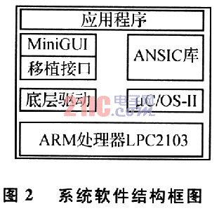
2.1 Control system minimum system The minimum system control system is shown in Figure 3. 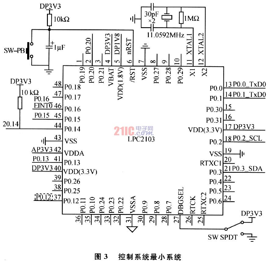
The LPC2103 minimum system requires analog and digital 3.3 V supplies and a core power supply of 1.8 V. To facilitate the baud rate setting, the crystal frequency is 11.059 2 MHz. PO. The 14-pin pull-up is disabled by a 10 kΩ resistor. The DBGSEL pin is tied high to enable the debug state, and is tied low during normal operation. A low-level reset circuit is formed by the RC circuit, and the SW-PB button is pressed to generate a processor reset signal.
2.2 GPS interface circuit The main function of this circuit is to receive the GPS module to send data, save it to the processor storage unit, and wait for the MiniGUI graphical user interface to display after processing. The GPS module uses a nine-pin serial port data output, RS232 level, and requires the SP3232E level conversion chip to be connected to the serial port O of the LPC2103. The SP3232E is an RS232 level shifting chip for 3 V operating power. The interface circuit is shown in Figure 4. 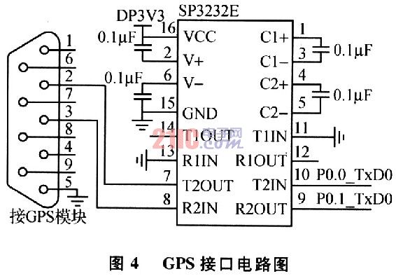
2.3 Keyboard Circuit This system uses 4×4 keypad for data input and analog mouse. S13 simulates the left button, S15 simulates the right button, and S9, S10, S11, and s14 simulate moving the mouse to the left, the bottom, the right, and the upper, respectively, and the rest are digital input keys. Due to the limited number of LPC2103 pins, the 7290 chip with I2C interface is used as the keyboard interface. The keyboard circuit reset and the system reset share the nRST reset signal. When a button is pressed, the interrupt signal is sent to the LPC2103 external interrupt processing unit via EINTO. The 7290's I2C interface adds a 4.7 kΩ pull-up resistor to the LPC2103's I2C serial bus interface, and the I/O pin is PO. 2 and PO. 3. The keyboard circuit is shown in Figure 5. 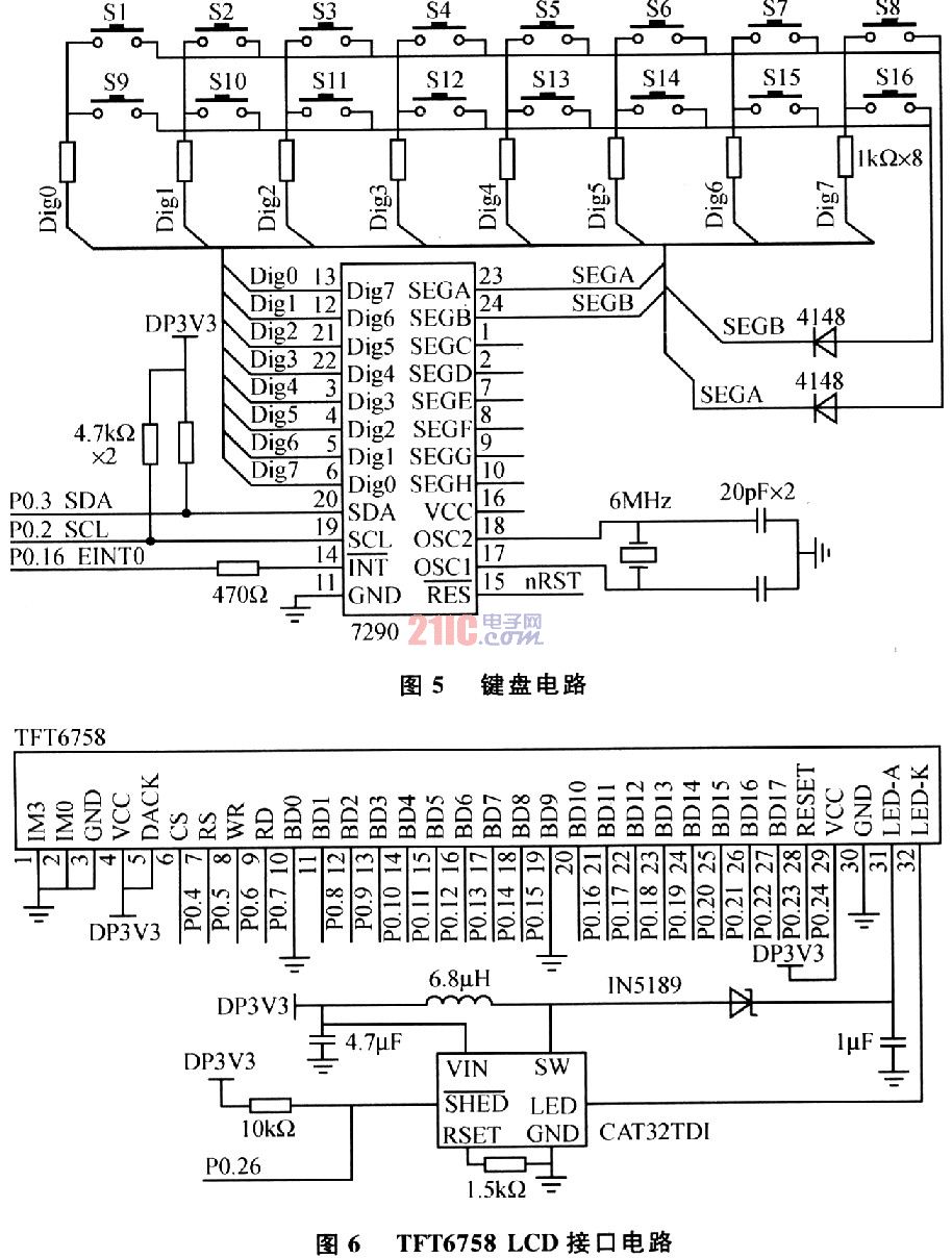
3.1 μC/OS-II porting on LPC2103 The processor-independent μC/OS-II source code can be downloaded directly from the Internet; the processor-related code needs to be written according to LPC2103, of which OS_CPU. H defines the constants, macros, and types associated with the processor. OS_CPU A. The functions implemented by ASM include: making the highest priority task ready for operation; task level switching; task switching after interruption; implementing a periodic clock source. OS CPU C. C mainly implements the initialization of the task stack. INCLUDES. The H main header file contains the header files required by the program to facilitate programming. Via OS_CFG. . The H file implements the configuration and cropping of the operating system.
3.2 MiniGUI Porting on LPC2103 (1) MiniGUI GAL porting is easy to port. MiniGUI introduces the graphics abstraction layer GAL, defines a set of abstract interfaces that do not depend on any special hardware, and all top-level graphics operations are built on abstract interfaces. , similar to the driver of the operating system. According to the hardware connection of the LCD driver module and LPC2103, write the LCD driver lcddriver. c and lcddriver. h. Write the graphics engine program commlcd according to the system hardware. c. The graphics engine program needs to call a function in the LCD driver.
(2) IAL transplantation of MiniGUI MiniGUI represents the input engine through the INPUT data structure, which is defined in ial. In the h file. The INPUT data structure defines a number of function pointers that point to the set IAL counterpart function to implement hardware input. The program input engine is comminput. c, through the underlying keyboard driver comm_driver. c Read keyboard input data. The driver emulates 16 keys into O~9 numeric keys and left and right mouse buttons.
(3) Cross-compilation of MiniGUI using ADSl. 2 Integrated development environment to build MiniGUI Lib project, add MiniGUI source file and configuration file under project, compile and generate MiniGUI_Lib. a library file. Lib. The a file is a POSIX thread library for the LPC2103 and μC/OS-II operating systems, and provides a memory management interface and an I/O interface. It occupies 3 MB of dynamic memory and uses 1 μC/OS-II mutex semaphore. Priority 42, the number of semaphores increased by 3 for each additional thread, the maximum number of threads is 16, the task priority is 43 to 58, and one MiniGUI thread stack (8 KB).
3.3 System Application Design (1) Main Program Design The main program flow is shown in Figure 7(a), which is used to complete the initialization of the operating system. The task O is created using the statement OSTaskCreate(Task0,(void*)O,&TaskStk[TaskStkLengh-1], 10); the MiniGUI main thread is created using the statement MiniGUI_app_entry(); a mailbox is created using the statement KevMbox=OSMboxCreate(NULL) for Pass the button message and finally start multitasking. 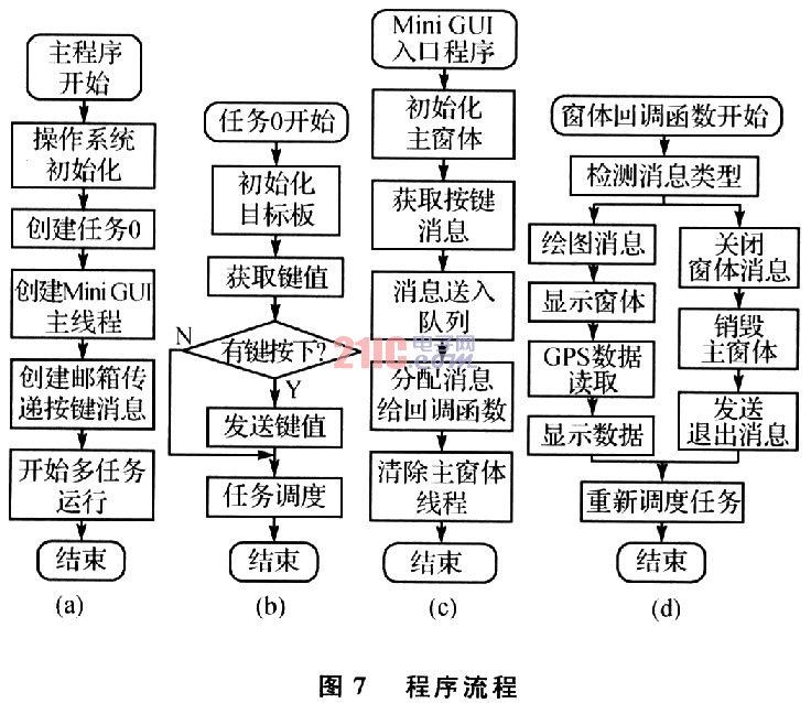
(2) Task O design The task O flow is shown in Figure 7 (b), used to complete the initialization of the system hardware. The key value is read by the input engine of the I2C interface. If there is a button press, the key value is sent to the KeyMbox mailbox through OSMboxPost (KeyMbo-x, (void*)&s_key_in). Run the CPU occupied resources and run other tasks through the post office OSTimeDly(5).
(3) MiniGUI entry program design The entry program is shown in Figure 7(c) to complete the message processing. Use the statement InitMainWindow() to initialize the form; use the statement ShowWindow(hMainWnd, SW_SHOWNORMAL) to display the form, where hMainWnd is the form handle; use the statement GetMessage(&Msg,hMainWnd)) to get the message, where the Msg data structure is used to save the message; The statement Trans-lateMessage(&Msg) puts the message into the queue; use the statement DispatchMessage(&Msg) to assign information to the form callback function; use the statement MainWindowThreadCleanup(hM-ainWnd) to clear the thread.
(4) MiniGUI form callback program design The form return function flow shown in Figure 7 (d), according to the message type to determine the program to be executed. If the message type is MSG-PAINT, first call the GPS data read and processing program, use the MiniGUI internal function TextOut (hdc, 10, 10, "display characters"), display the characters at the specified position; finally call the μC/OS-II system The function OSTimeDly (100) starts task scheduling. If the message type is MSG_CLOSE, destroy the form with the statement DestroyMainWindow(hWnd); send the exit message with the statement PostQuitMessage(hWnd). 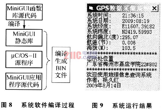
The GPS module is connected to the serial port 0 of the LPC2103, and placed outside. The generated executable file is programmed into the flash of the LPC2103 and powered on. The running result is shown in Figure 9.