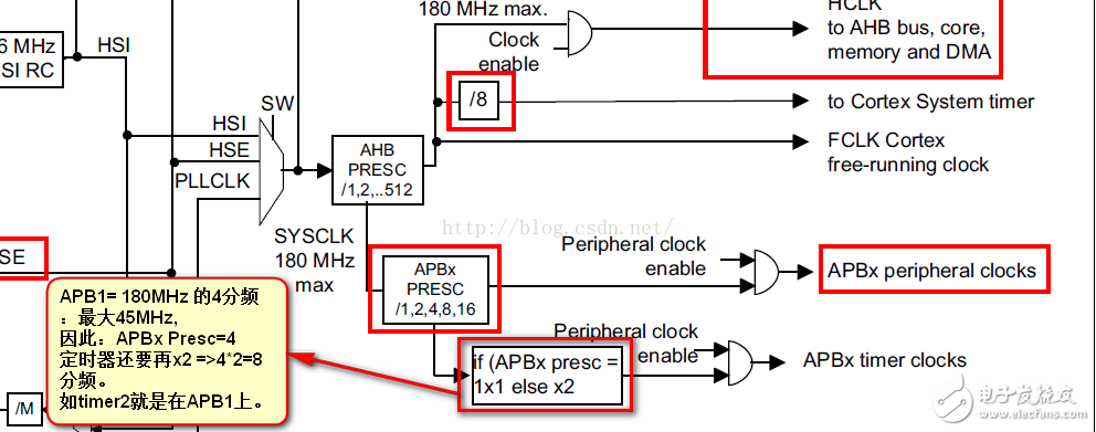
In the electronic age, hardware is developing by leaps and bounds, and the frequency is rising. The current frequency of STM32 series, Cortex M series, and Cortex-M4 is 180MHz, which is basically the same as the previous ARM7/9 frequency, and Cortex-M7 , the frequency is higher, BGA package and SDRAM DDR appeared. It seems that processors are becoming more and more popular, and the networking of electronic devices on the Internet of Things is becoming more and more popular. The continuous reduction of hardware costs is the general trend. Therefore, as an electronic designer, you must continue to learn and master more technologies. Knowledge and foundation, so that they will not be quickly eliminated by society. I recently bought a ready-made STM32F429 Discovery development board, and I want to try the transplantation and application of a larger embedded operating system such as RTEMS. Because of the foundation of STM32F103/107 and familiarity with hardware and firmware libraries, STM32F429 is actually very easy to start. Let's try the timer interrupt point LED first, mainly to organize the project directory. I changed it according to the project directory that I have been using STM32F103 before, and used the latest firmware library V1.6.1 of STM32F4XX. As for why I don't directly operate the registers, I think, although I am a hardware origin, I have a deeper understanding of the processor by engaging in registers. However, after all, there are too many registers. With the library, you can encapsulate it, so that you can get started quickly. If you need to check the register, you can also check it. Using the firmware library can reduce some errors. After all, we are doing applications, and we must first learn to use the CPU to achieve the functions we want. The project directory is as follows: The latest Keil MDK V5.17 version is used here, and the device library of STM32F4XX needs to be further downloaded. The ST-Link download program that comes with it is used here, of course, it is also possible to use Jlink. The system timer of STM32F429 is originally a frequency division of 180MHz of the system clock. This can be seen in the reference manual of STM32F4XX, which introduces the framework of the clock RCC part. I calculated it here for the timing of 1S. The following is the main program of TIm2.c. TIm2.h is just a function declaration. /********************(C)COPYRIGHT2016**************************** * *File name: TIm2.c *Description: Timer TImer2 test routine *Experimental platform: STM32F429ZIT6 *Library version: V1.6.1 * *Writing date: 2016-05-02 *Modified date: *author: **************************************************** ****************************/ #include "Tim2.h" /* *Function name: TIM2_NVIC_Configuration *Description: TIM2 interrupt priority configuration *input: none *output: none */ voidTIM2_NVIC_Configuration(void) { NVIC_InitTypeDefNVIC_InitStructure; NVIC_PriorityGroupConfig(NVIC_PriorityGroup_4); NVIC_InitStructure.NVIC_IRQChannel=TIM2_IRQn; NVIC_InitStructure.NVIC_IRQChannelPreemptionPriority=3; NVIC_InitStructure.NVIC_IRQChannelSubPriority=0; NVIC_InitStructure.NVIC_IRQChannelCmd=ENABLE; NVIC_Init(&NVIC_InitStructure); } /*TIM_Period--1000TIM_Prescaler--(22500-1)--"The interrupt period is ((1/180000000)*8)*22500*1000=1S1 second timer*/ voidTIM2_Configuration(void) { TIM_TimeBaseInitTypeDefTIM_TimeBaseStructure; RCC_APB1PeriphClockCmd(RCC_APB1Periph_TIM2, ENABLE); TIM_DeInit(TIM2); TIM_TimeBaseStructure.TIM_Period=1000;/*The value of the auto-reload register period (count value)*/ /* Generate an update or interrupt after accumulating TIM_Period frequencies*/ TIM_TimeBaseStructure.TIM_Prescaler=(22500-1);/*Clock prescaler(180M/8)/22500*/ TIM_TimeBaseStructure.TIM_ClockDivision=TIM_CKD_DIV1;/*Sampling frequency division*/ TIM_TimeBaseStructure.TIM_CounterMode=TIM_CounterMode_Up;/*Counter up mode*/ TIM_TimeBaseInit(TIM2, &TIM_TimeBaseStructure); TIM_ClearFlag(TIM2, TIM_FLAG_Update); /*Clear overflow interrupt flag*/ TIM_ITConfig(TIM2, TIM_IT_Update, ENABLE); TIM_Cmd(TIM2, ENABLE); /*Turn on the clock*/ //RCC_APB1PeriphClockCmd(RCC_APB1Periph_TIM2, DISABLE);/*Close first and wait for use*/ } /* *Function name: TIM2_Config *Description: TIM2 configuration *input: none *output: none */ voidTIM2_Config(void) { TIM2_Configuration(); TIM2_NVIC_Configuration(); } /********************(C)COPYRIGHT2016*ENDOFFILE************/ The following is: led.c file. /********************(C)COPYRIGHT2014**************************** ** *File name: led.c *Description: led application function library *experiment platform: *Hardware connection: ----------------------- *|PG14-LED1 (RUN)| *----------------------- *Library version: ST3.5.0 *Writing date: 2014-11-04 *Modified date: *author: **************************************************** ****************************/ #include "led.h" /* *Function name: LED_GPIO_Config *input: none *output: none */ voidLED_GPIO_Config(void) { /*Define a structure of type GPIO_InitTypeDef*/ GPIO_InitTypeDefGPIO_InitStructure; /*Turn on the peripheral clock of GPIOx of LED1*/ RCC_AHB1PeriphClockCmd(RCC_LED1, ENABLE); /*Select the LED1GPIOx pin to control*/ GPIO_InitStructure.GPIO_Pin=GPIO_Pin_LED1; /* Set the pin mode to general push-pull output */ GPIO_InitStructure.GPIO_Mode=GPIO_Mode_OUT; /*Set the pin rate to 50MHz*/ GPIO_InitStructure.GPIO_Speed=GPIO_Fast_Speed; /* Set to push-pull output mode */ GPIO_InitStructure.GPIO_OType=GPIO_OType_PP; /* set to pull up */ GPIO_InitStructure.GPIO_PuPd=GPIO_PuPd_UP; /*Call the library function to initialize the GPIOx of LED1*/
DADNCELL alkaline zinc-manganese dry
battery has the characteristics of low self-discharge, which is suitable for
household batch procurement storage, and has the discharge performance of
continuous discharge time with more long-lasting and large instantaneous discharge.
Widely used in flashlights, smart door locks, infrared thermometers, cameras,
flash lights, razors, electric toys, instruments, high-power remote control,
Bluetooth wireless mouse keyboards and other common household electronic
equipment instruments. DADNCELL battery advocates providing a more comfortable and smooth
power supply experience for household appliances. The alkaline battery capacity
and discharge time of the same model of DADNCELL battery have reached four to seven times
that of ordinary batteries, respectively.
The performance difference between
the two is greater at high and low temperatures, because its unique internal
components are structure and battery materials with better performance, and the
power capacity and electrical performance can be improved.
At
present, all types of batteries developed by DADNCELL Lab do not involve any heavy metals in
production, use and waste. They are green and environmentally friendly and can
be treated with domestic waste.
1.5V Am-1 Alkaline Cells,All-Purpose Alkaline Batteries,Premium Alkaline D Cell Batteries,Batteries Camera Meters Shandong Huachuang Times Optoelectronics Technology Co., Ltd. , https://www.dadncell.com