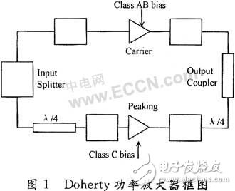
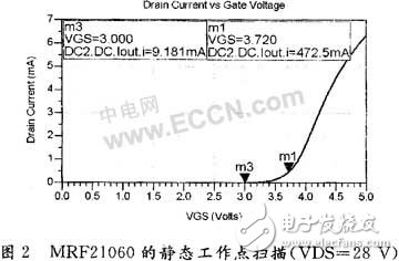
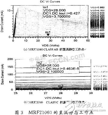
RF power amplifiers are widely used in various wireless communication transmitting devices. The cost ratio of linear power amplifier in the base station is about 1/3. It is very important to solve the linearization problem of the power amplifier effectively and at low cost. High-efficiency and high-linearity power amplifier research is a hot topic, especially for WCDMA power amplifiers in recent years. At present, there are only a few companies that can produce more than 10 W WCDMA power amplifiers in China, because WCD-MA power amplifiers have higher linearity requirements. The WCDMA power amplifier produced by the ordinary back-off method can only achieve a few watts in accordance with the index. This power is not enough for the base station and can only be used in the general small-scale repeater. The linearity and efficiency of the power amplifier is the focus of designing the power amplifier. In terms of linearity, the feedforward structure is a relatively mature structure, which is widely used in modern communication systems. Digital predistortion is considered as the direction of power amplifier linearization in the industry. With the development of modern communication, efficiency has begun to attract more and more attention. The Doherty method is considered to be the most promising structure for improving efficiency. The structure of feedforward and Doherty structure or the structure of digital predistortion combined with Doherty is of great value. 1.1 Overview of Doherty Power Amplifier Principle The Doherty structure consists of two power amplifiers: one main power amplifier, one auxiliary power amplifier, the main power amplifier working in class B or class AB, and the auxiliary power amplifier working in class C. The two amplifiers do not work in turn, but the main amplifier always works, and the auxiliary amplifier works until the set peak (this amplifier is also called peak ampli-fier). The 90° quarter-wavelength line behind the main power amplifier is impedance transformation. The purpose is to reduce the apparent impedance of the main power amplifier when the auxiliary power amplifier works, and to ensure that the auxiliary power amplifier works and the circuit behind it. The active load impedance becomes lower, so that the main power amplifier output current becomes larger. Since the main power amplifier has a quarter-wavelength line behind it, in order to make the two power amplifier outputs in phase, a 90° phase shift is also required in front of the auxiliary power amplifier. As shown in Figure 1. The main power amplifier works in class B. When the input signal is relatively small, only the main power amplifier is in working state; when the output voltage of the tube reaches the peak saturation point, the theoretical efficiency can reach 78.5%. If the excitation is doubled at this time, the tube will be saturated at half the peak and the efficiency will reach 78.5%. At this time, the auxiliary amplifier will also work with the main amplifier (category C, the threshold is set to Half of the excitation signal voltage). The introduction of the auxiliary power amplifier makes the load decrease from the perspective of the main power amplifier, because the auxiliary power amplifier acts as a load on the load equivalent to a negative impedance in series, so even if the output voltage of the main power amplifier is saturated, the output power is due to the load. The decrease continues to increase (the current flowing through the load becomes larger). When the peak of the excitation is reached, the auxiliary power amplifier also reaches its maximum efficiency, so that the efficiency of the two power amplifiers is much higher than the efficiency of the single class B power amplifier. The maximum efficiency of a single Class B amplifier is 78.5% at the peak, and now 78.5% efficiency occurs at half the peak. So this system structure can achieve high efficiency (maximum output efficiency per amplifier). 1.2 Doherty Power Amplifier Design According to the rated power of 30 W, the output gain is 50 dB, and the operating frequency is 2 110 to 2 170 MHz. To design a Doherty power amplifier, you should first select the components, then select the appropriate static operating point and set the bias circuit. Then perform impedance matching, and finally design a 90° combiner to synthesize the main and auxiliary power amplifier circuits. 1.2.1 Power Amplifier Selection and Amplifier Bias Design The power amplifier is first selected based on the specifications. RF power amplifiers mainly use Motorola's LDMOS tubes, which have a market share of more than 70%. LDMOS devices are also particularly suitable for CDMA, W-CDMA, TETRA, digital terrestrial TV, etc., requiring wide frequency range, high linearity and service life. High demanding applications. In addition, since the total amplifier output gain is 50 dB, a multi-stage power amplifier should be used. Since the highest efficiency of the Doherty power amplifier is achieved at approximately 6 dB backoff, the power amplifier is selected to be two Motorola tubes MRF21060, which have a total power of 120 W at maximum power operation and 1/4 of the back-off (6) dB) gives 30 W. To design a Doherty power amplifier, one of the tubes needs to be operated in Class AB or Class B operation, while the static operating point of the other tube is selected in Class C operation. Perform a static operating point scan of the MRF21060 of the LDMOS tube and select a suitable static operating point, as shown in Figure 2. According to Doherty's technical requirements, the choice of power amplifier bias should be such that the main amplifier is saturated when the auxiliary amplifier starts to operate, in order to achieve a relatively high efficiency. When the MRF21060 is selected for Class AB operation, the static operating point is approximately 3.7 V. When you select the Class C working state, you choose to work at 2.1 V. The quiescent operating current and voltage for the two bias states are shown in Figure 3. 1.2.2 Circuit Matching Design
Brand Name: OEM
Product Name: Multi USB Charger
Use: Mobile Phone
Place of Origin: Guangdong, China (Mainland)
Port: 6 port
Input: AC100-240V 50/60HZ
Size: 90*70*16mm
Weight: 250g
Materials: PC+ABS
Color: Black/White
Warranty: 1 year
Multi USB Charger,Multi Usb Wall Charger,Multiple Usb Port Charger,Multi Port USB Charger Shenzhen Waweis Technology Co., Ltd. , https://www.szwaweischarger.com