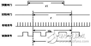
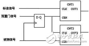
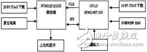
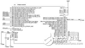
In electronic engineering, resource exploration, instrumentation and other related applications, frequency measurement is one of the most basic and most common measurement in electronic measurement technology. Frequency meter is also an indispensable measurement tool for engineers and technicians. However, the traditional frequency measurement method has great limitations in practical applications. The measurement accuracy of the frequency meter based on the traditional frequency measurement principle will vary with the frequency of the measured signal. The traditional direct frequency measurement method will measure the accuracy. As the frequency of the measured signal decreases, the measurement accuracy of the measurement method will decrease as the frequency of the measured signal increases. In this paper, a digital frequency meter based on ARM and CPLD wideband is proposed. The microcontroller STM32 is used as the core control chip, and the CPLD programmable logic device is used to realize the precision measurement of the gate measurement technology. Frequency range: 1Hz ~ 200MHz, resolution is 0.1Hz, frequency measurement relative error of one millionth. Period measurement: The signal measurement range and accuracy requirements are the same as the frequency measurement function. Duty cycle measurement: Accuracy is 99%. Counting range: 0~1000000000, can be manually paused and reset. Power consumption: 5V & TImes; 250mA = 1.25W. Commonly used direct frequency measurement methods mainly include two methods: frequency measurement method and measurement period method. The frequency measurement method records the number of change cycles (or the number of pulses) Nx of the measured signal within the determined gate time Tw, and the frequency of the measured signal is: fx=Nx/Tw. The measurement period method needs to have the frequency fs of the standard signal. In the period Tx of the signal to be tested, the number of cycles of the standard frequency is recorded, and the frequency of the signal to be measured is: fx=fs/Ns. The count values ​​of these two methods produce ±1 word error, and the test accuracy is related to the value Nx or Ns recorded in the counter. In order to ensure the test accuracy, the measurement cycle method is generally adopted for the low frequency signal, and the frequency measurement method is adopted for the high frequency signal. However, due to the inconvenience of the test, an equal-precision frequency measurement method was proposed. The equal-precision frequency measurement method is developed on the basis of the direct frequency measurement method. Its gate time is not a fixed value, but an integer multiple of the period of the signal to be measured, that is, synchronized with the signal to be measured. The control timing diagram of the equal-precision frequency measurement system is shown in Figure 1. Figure 1 Control timing diagram of the equal-precision frequency measurement system During the measurement process, two counters count the standard signal and the measured signal simultaneously. First, the gate open signal (preset gate rising edge) is given. At this time, the counter does not start counting, but the counter does not start counting until the rising edge of the signal under test arrives. Then, when the preset gate close signal (falling edge) comes, the counter does not stop counting immediately, but waits until the rising edge of the measured number comes, and ends the counting to complete a measurement process. It can be seen that the actual gate time r is not strictly equal to the preset gate time r1, but the difference does not exceed one cycle of the signal under test. Set in an actual gate time r, the count value of the counter to the measured signal is Nx, the count value of the standard signal is Ns, and the frequency of the standard signal is fs, then the frequency of the measured signal is as shown in equation (1). Figure 2 is a logic block diagram of equal-precision frequency measurement. CNT1 and CNT2 are two controllable counters. The standard frequency signal fs signal is input from the clock input terminal CLK of CNT1. The shaped signal fx after being shaped is input from the clock input terminal CLK of CNT2. . The CEN input in each counter is the clock enable and controls the clock input. When the preset gate signal is high (preset time starts), the rising edge of the signal under test passes through the output of the D flip-flop, and simultaneously starts counting of two counters; likewise, when the preset gate signal is low ( At the end of the preset time, the rising edge of the signal under test passes through the output of the D flip-flop and the counter is turned off. Figure 2 Equal-precision frequency measurement logic block diagram The ST chip's 32-bit processor STM32F103C8 is used as the master chip and combined with the high-reliability programmable logic device EPM240T100C5 to design a frequency meter. The features of the STM32F103C8 are as follows: (1) The highest frequency can reach 72MHz, with 128/64KB FLASH, 1.25DMIPS/MHz, and can access the 0 wait cycle memory. (2) The power supply voltage range is 2.0 to 3.6V. The 8MHz high-speed crystal oscillator is embedded. It can also be supplied with an external clock. This system uses the CPLD clock to divide the frequency. (3) The download mode can use Serial Wire Debug (SWD) interface and JTAG interface. This system uses JTAG download interface. The features of the EPM240T100C5 are as follows: (1) The internal clock frequency is 300MHz. The system uses an active crystal oscillator of 50MHz. (2) The on-chip voltage regulator supports 3.3V, 2.5V or 1.8V power input. The system uses 3.3V voltage supply. (3) The download mode uses a 10-pin JTAG interface. 1 system hardware block diagram The system controls the internal logic unit by sending data and commands to the CPLD chip EPM240T100 via the SPI bus through control of the STM32F103C8 microcontroller. The EPM240T100 uses an external active crystal oscillator with a 50MHz supply and divides by 12.5MHz as the input clock to the CPU. The hardware structure of the system is shown in Figure 3. The utility model comprises a main control chip module, a JTAG download module, a reset circuit module, a host computer display module and a measured input module. Figure 3 system block diagram 2 system digital circuit design The principle of the microcontroller is shown in Figure 4. The system processor uses STM2F103C8, the clock is divided by CPLD to the CPU, the data and commands are transmitted to the CPLD through SPI, and then sent to the host computer through the serial port RS232. Figure 4 Microcontroller schematic Fan Motor,Air Cooler Motor,Ac Motor Air Cooler,Asynchronous Fan Motor WUJIANG JINLONG ELECTRIC APPLIANCE CO., LTD , https://www.jinlongmotor.com