Implementing Red Pitaya Open Source Instrument with Zynq SoC
The latest Red Pitaya program helps to easily and cost-effectively develop many different versions of the instrument from a single platform.
In the early days of the electronics industry, test and measurement equipment such as oscilloscopes and signal generators were fixed in function and could perform only a few clear tasks. Over the past few decades, manufacturers have used DSP's programmable features to tailor a rich feature set for specific applications. However, only the manufacturer can program these instruments and determine their final feature set before the product leaves the factory.
Although most instruments on the market today have a rich feature set, they do not meet the precise functions required by a customer's specific project. This is a large-scale construction of smaller subsystems in scientific research institutions and universities around the world. This is especially true for interdisciplinary research groups of complex systems. In scientific research, equipment that is more elaborate than the ones provided by the manufacturer is often required. In general, high-speed feedback systems involve two (or more) instrument subsystems that require very low jitter and hard real-time response, often with integration problems. Often the instrument interface is difficult to achieve the desired overall integrated system performance. Closed source and DSP-oriented instruments do not allow such integration.
Engineers at InstrumentaTIon Technologies have been wondering what would happen if a user-programmable, user-customizable open source instrument (or signal processing platform) was developed? To this end, we have developed a "Red Pitaya" small test board that is supported by the open source development ecosystem. The Red Pitaya system is expected to replace many standard test and measurement instruments at significantly lower prices with a single reconfigurable device. Figure 1 shows the system architecture of Red Pitaya. This is a new instrument (signal processing system) with multiple analog/digital inputs and outputs.
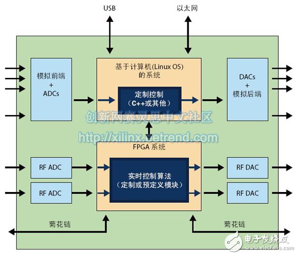
Figure 1 - Red Pitaya System Architecture
Instruments with ideal system architectures typically require superior performance in both analog and digital domains. The ever-increasing frequency of the analog domain still imposes stringent requirements on the noise floor and measurement performance of the instrument. The digital domain is gaining momentum due to its stability, strong noise immunity, time invariance, ability to perform highly complex processing, and the ability to combine with standard connectivity. Therefore, signal processing is gradually transitioning from the analog domain to the digital domain.
The basic method of the new signal processing system is to use general-purpose electronic equipment in the analog front end, and use high-speed ADC for signal sampling in the processing chain. The digital side tends to process the signals first and then send them to the DAC in the processing chain as late as possible. The analog backend also uses generic electronic devices as much as possible. With this architecture, all of the features of the processing/measurement system are concentrated in the digital domain, and analog electronics remain simple and versatile. This new digital-based architecture provides an opportunity to customize a range of tasks across multiple application domains through hardware, perhaps only by the bandwidth of the analog front-end backend and the computing resources of the digital domain (primarily FPGA and CPU resources). limit.
From a speed perspective, there are two main types of processing chains on Red Pitaya. One type of processing chain is a signal processing chain with a bandwidth of about 50MHz realized by the extremely high speed and very low jitter hard real-time processing function of FPGA; the other processing chain is realized by CPU, which may be used to run a hard real-time operating system. The bandwidth of the signal processing chain is about 50KHz.
The embedded digital signal processing function in the instrument is primarily responsible for reducing the data from the instrument input to the processing result output.
In our experience, using FPGAs and CPUs as basic modules in signal processing systems in reconfigurable instruments has been a successful combination. This combination provides a great deal of freedom for signal processing partial partitioning between high-performance FPGAs and easy-to-program CPUs. In particular, almost all instruments face the problem of reducing the amount of input data from the original sampling point to the instrument output point. For example, an oscilloscope chart only needs to maintain 1,000 points.
Examples of typical test results include the signal diagram of the oscilloscope, the frequency domain diagram of the frequency analyzer, or the positional trajectory map of the basketball player's position obtained by processing the ceiling camera output. All of these measured outputs represent much less data than the instrument's raw signal input data. The input data is sampled at very high frequencies. The reduction of data from the input of the instrument to the output of the processing result is the main work of the digital signal processing function embedded in the instrument.
Embedding both the FPGA and the CPU in the signal processing system gives developers the freedom to decide how to distribute DSP processing tasks between the FPGA and the CPU. In terms of the suitability of the process, there is a slight difference between the two, but both can perform digital signal processing. In general FPGAs are suitable for processing ultra-high-speed but simple DSP operations, but not suitable for complex program operations (procedural operaTIons). The CPU is good at processing slower and more complicated program operations. In addition, the CPU is also good at running standard interactive interfaces such as web servers. Although FPGA development tools have been greatly improved in recent years, it is still relatively simple to write program software running on the CPU compared with RTL coding and digital structure synthesis in FPGA.
The free allocation of DSP processing between the FPGA and the CPU offers another advantage in that it can quickly prototype a system with limited performance but full functionality. Execute most of the DSP processing work on the CPU, not only can be prototyped in the early stage of project development, which is suitable for marketing purposes. At the same time, in the later stage of project development, this method can be used to smoothly transplant the key performance parts of DSP to FPGA. To create a final product with the same functionality but complete performance.
Figure 2 is an example of the allocation of DSP algorithms between the FPGA and the CPU. During the development process, the partition boundaries between the FPGA and the CPU can vary. Since the DSP processing is split, the partially processed data must be transferred back and forth between the FPGA and the CPU. Therefore, the bus speed between the two is extremely important to prevent additional processing delays.
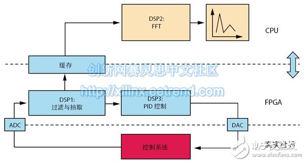
Figure 2 - DSP Algorithm Allocation Between FPGA and CPU
Red Pitaya
The Red Pitaya system shown in Figure 3 is built on the Xilinx Zynq®-7010 All Programmable SoC. Red Pitaya's high-speed dual-channel 125Msps signal acquisition and signal generation capabilities, combined with the FPGA DSP processing capabilities in between, form a hard real-time feedback loop. In addition to high-speed signal processing, the system has several slower (approximately 100KHz) I/O channels and multiple digital I/Os using Xilinx Analog Mixed-Signal (AMS) technology (Figure 4). Distributed processing can be achieved if a user daisy-chains multiple Red Pitaya modules using a high-speed serial daisy-chain connector. In this way, users can build complex systems with more I/O ports by interconnecting multiple Red Pitaya subsystems. The CPU is responsible for running the Linux operating system and provides support for 1000Base-T Ethernet, USB OTG, Micro SD storage and USB serial consoles.
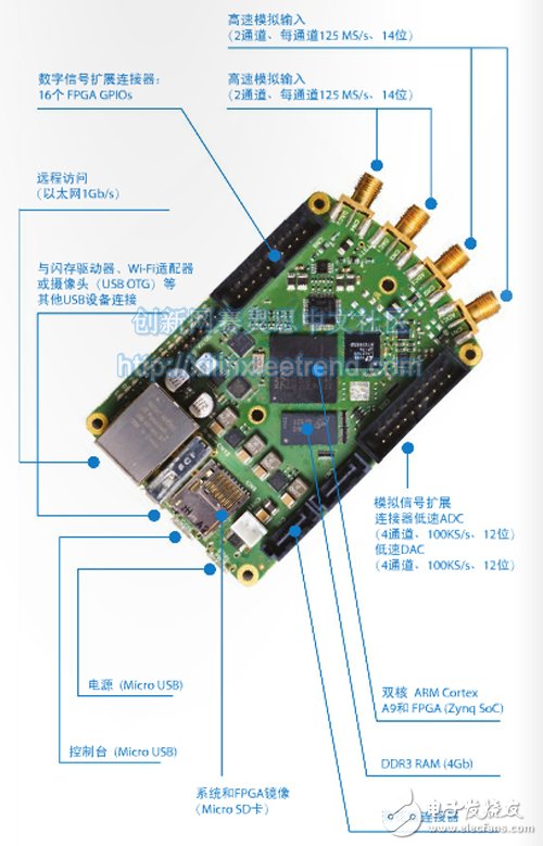
Figure 3 - Universal Red Pitaya Instrument Platform
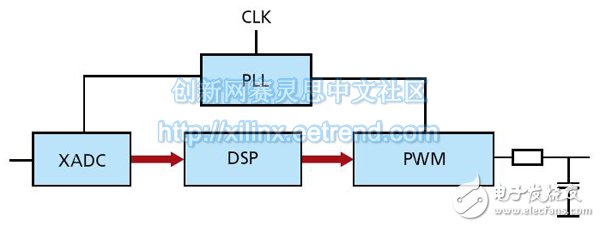
Figure 4 - Xilinx AMS Technology (XADC) combined with PWM-based output
Initial applications for Red Pitaya instruments include dual-channel 125Msps oscilloscopes, spectrum analyzers, signal processors, and PID controllers. Red Pitaya instruments and accompanying applications and ecosystems will be available in December 2013. The appeal of its open source is that enthusiasts can develop custom applications based on their specific needs. As with any open source customization, others have the opportunity to use improved or brand new instruments or applications. The Red Pitaya ecosystem is expected to continue to evolve and improve many other applications.
Pp Velcro Braided Sleeve,Velcro Braided Cable Sleeve,Kevlar Braided Sleeving,Velcro Expandable Braided Sleeve Cable Sock
Shenzhen Huiyunhai Tech.Co., Ltd. , https://www.cablesleevefactory.com