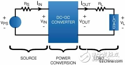
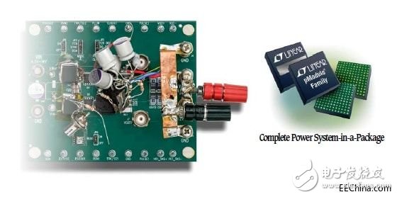
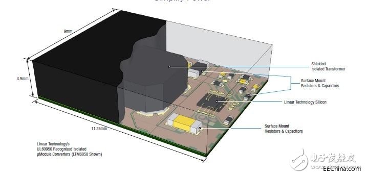
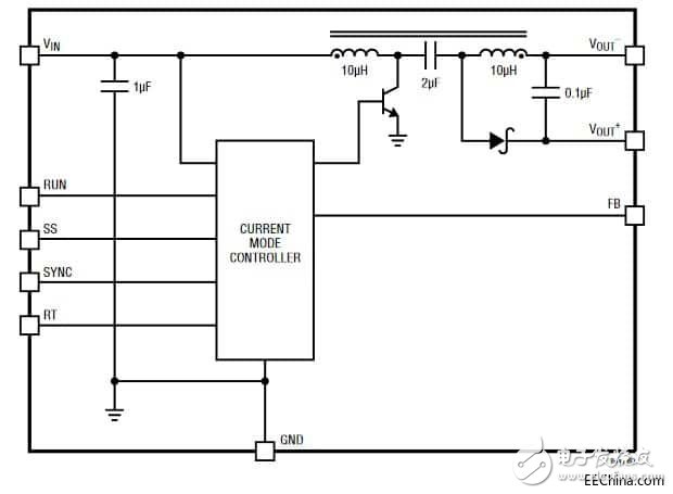
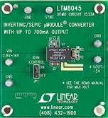
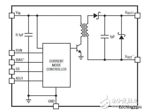
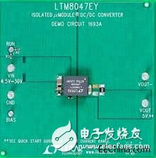
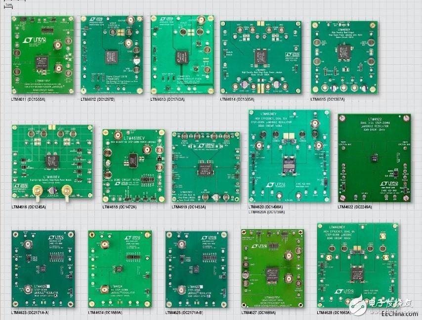
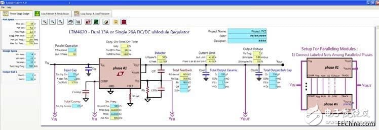
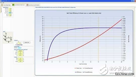
Nowadays, it is not difficult to design a basic and easy-to-use DC/DC power regulator (or called power converter) by using existing components, reference designs, tools, and resources. The designer needs to properly control Combining IC, MOSFET transistors, driving circuits, and some passive components, the whole design is theoretically completed, which can convert and stabilize the input DC voltage while outputting the DC voltage (see Figure 1). Figure 1: In principle, the function of the voltage stabilizer is very simple and clear: a stable DC input power supply is adopted, and the output DC voltage is provided to the system after strict adjustment. However, this is only theoretical, and we are still facing harsh reality. It is no longer enough to make a "relatively good" design, although such a design can meet some basic performance parameters, such as output accuracy, voltage regulation effect, etc. , But remember that these "basic" parameters are only a small part of the modern regulators must have, in addition to the increasingly stringent requirements for dynamic performance, efficiency of various loads, and electromagnetic interference/radio frequency interference (EMI/RFI) It is also getting more and more severe. Let's discuss some of the key points in the many requirements of power regulators. The first is to provide sufficient current under specific output voltage requirements, with a tolerance of 1% to 3% (typical range), and some situations require more stringent requirements. Then the dynamic performance needs to respond quickly to line and load changes, but in order to minimize fluctuations or instability, the regulator must also have protection functions against various faults, such as overcurrent (including load short-circuit), Overvoltage/undervoltage and overheating conditions. For a variety of reasons, efficiency and EMI/RFI standards are usually the most difficult to meet. First of all, these requirements are very strict. In addition, these standards differ from country to region, so they need to be fully understood. In order to make it more challenging, the efficiency of the power supply must meet the requirements of other operating modes such as active and standby. In addition, efficiency and EMI/RFI performance must be tested and carefully conducted by appropriate laboratories or institutions, PCB layout and BOM list A small change will affect efficiency and EMI/RFI performance, so comprehensive testing and certification is required. In addition to these basic performance requirements, the regulator must also ensure small size, low cost, simple BOM devices, and no special steps (especially manual operations) in the production and assembly of power-related components, such as capacitors, resistors, and MOSFETs. Or IGBTs and heat sinks, etc., there will be intersections and conflicts between these requirements, so effective trade-off analysis and compromise are essential. Start from power level Of course, not all power supply regulator designs are difficult, but the difficulty of design and hands-on production increases with the increase of power/current. It is relatively simple to design low-power power supplies that provide less than 1A or 2A current. Such a design Many low-dropout ("linear") regulators (LDOs) or switching regulators available on the market can be used. The performance of these components is also moderate and can meet the design performance parameters in most cases. The challenges faced by the design of the medium power range are increasing, especially the current range is between 2A and 10A. As the current and components become larger and larger, the problems and defects of the previous miniaturization design are gradually enlarged. The manufacturer provides The reference designs have been tested and verified. It is convenient for us to adopt these designs at the beginning, but it is not guaranteed to be suitable for all scenarios. For applications with a current range of tens of amperes or higher, the design and manufacturing difficulties of power regulators will increase exponentially. These designs require the use of larger-volume components, more power dissipation, and higher IR radiation, and increase the potential problems of EMI/RFI, in short, there are too many factors that make it difficult to design the regulator, some components may require mounting brackets or screws, larger heat sinks, design air In the flow path, it is difficult to perform performance testing at higher currents, because it is mainly to test whether the design meets the stricter efficiency and EMI/RFI requirements. If the power supply must be electrically isolated (which is often required in terms of safety and performance), the design must comply with high-voltage isolation standards and compatibility requirements between sub-components. Therefore, designers of mid-range and high-power regulators often face longer product launches, more expensive BOMs, and a high degree of uncertainty and risk, because the performance of regulators appears to be more and more in the design of end products Important, especially when it comes to product acceptance and promotion. In fact, if you only provide a "blank" design implementation without a good reference design as a starting point, you will undoubtedly face arduous challenges. Even if there is a reference design, complicated debugging and other issues will occur as the current (or power) increases. . Of course, there are some alternatives to MIY (designed by yourself), such as purchasing a complete voltage regulator design. Traditionally, the boundary between manufacture and purchase is divided according to 2A and 10A current: less than 2A can be designed and manufactured by yourself, and more than 10A can choose to purchase mature designs. It depends on what scenario is used to make a certain compromise. In most cases, purchase options usually take into account the size and rating of various modules, and they are generally (but not always) encapsulated in epoxy resin black boxes. These modules provide basic functions and Required performance, but it is generally relatively large, heavy, and inflexible, and there are only a few modules to choose from. New buying options provide a new perspective In addition to the two methods of "manufacture yourself" and "purchase plan", there is an alternative solution that can solve most mid-range systems and the increasingly stringent efficiency issues, EMI/RFI, and market pressures they face: the alternative is Using the μModule® series of high-performance regulators introduced by Linear Technology (LTC), currently Linear Technology (LTC) is a subsidiary of ADI. As shown in Figure 2, these embedded devices combine advanced design, components, and packaging to overcome modularization issues and some limitations. There are more options for design scenarios that require "self-made", but only for those low-end Only the low current application of 2A has practical significance. Figure 2: μModule DC/DC regulator replaces the complex PC board, no longer need to use active and passive discrete components, and ultimately is a simple and miniature embedded device At present, the μModule module is composed of more than 100 different units, divided into 15 series to meet the performance requirements of various application scenarios. In addition, it has more than 30 types of miniature packages, and the device area ranges from 6.25 &TImes; 6.25mm to 16 &TImes; 11.9mm, height from 1.82mm to 5.02mm, each μModule is a fully integrated DC/DC power solution, as a complete system-in-package it has: inductor, MOSFET, DC/DC regulator IC and other support The component (see Figure 3), the output current range from 2A to 20A, and the voltage range from 1.8VDC to 58VDC. Figure 3: Each μModule unit includes the necessary inductors, MOSFETs, regulator ICs and all supporting components. It is a highly integrated package unit However, the μModule unit is not only a simple and basic DC-in/DC-out regulator, the current version also includes the following features: • Ultra-low noise, which can meet the strict EN55022 Class B requirements of some applications • Seamless buck-boost conversion, which is very important when the nominal output value of the power supply voltage (fully charged) falls below this value (discharged). • A single μModule supports multiple outputs (2/3/4 or 5 channels), allowing output current sharing, ensuring current load during switching operations and output sequence power-up • Digital input/output (I/O) interface, these regulators can be "read" status and "write" setting operations through the serial bus. In these cases, close inspection and control can be performed • Remote sensing can offset the impact of IR drop between the regulator output and the load in the case of higher current • Support current sharing (or parallel connection) between multiple μModule regulators to provide high power while evenly distributing current to the load • Polarity reversal, when the given output voltage is positive, the regulator output must be negative • Tunable compensation, adjust compensation according to load characteristics and output capacitor type and quantity to achieve accurate output and transient response, so as to realize the loop change response of the regulator • Ultra-thin package, so the voltage regulator device can be tightly mounted on the bottom of the circuit board, or embedded between FPGA (programmable gate array) or ASIC (application-specific integrated circuit), and can also be placed on a heat sink/cooling plate the top of. Two μModule application examples show the diversity of functional features In view of the 15 series of μModule products with so many devices, there is no clear typical unit module or two similar examples, so we choose two application examples to show a variety of available functions and features. LMT8045 (see Figure 4) is a DC/DC converter that can be configured as a SEPIC (single-ended primary inductance converter) or reverse converter by simply grounding some output power. In the SEPIC configuration, the regulated output voltage can be higher, lower or equal to the input voltage. LTM8045 includes power devices, inductors, control circuits and passive components. The necessary conditions for using it are input and output capacitors and small resistors to set Output voltage and switching frequency, and other components can be used to control soft start and under-voltage lockout. The example board (see Figure 5) simplifies the settings for various modes and performance evaluations. Figure 4: LMT8045 is a DC/DC μModule unit that supports 2.8V to 18V input and multi-topology structure. It can provide up to 700mA of output current in boost mode or buck mode Figure 5: The sample board allows users to evaluate the performance of the board in a variety of different modes LTM8047 (Figure 6) is an isolated flyback μModule DC/DC converter with an isolation rating of 725VDC. The package includes the switching controller, power switch, isolation transformer and all supporting components. Its operating input voltage range is from 3.1V to 32V, and its output operating voltage range is from 2.5V to 12V. These settings are all adjusted by a resistor. In this design, output, input, and bypass capacitors are necessary (Figure 7). Figure 6: Using LTM8047 μModule, users can simply and quickly implement a converter capable of isolating 750VDC, adopt a small package, and provide high performance at the same time Figure 7: This sample board allows users to use an independent compatible design without having to consider detailed isolation details Some advantages of μModule: some are obvious, some are not obvious The first advantage of μModule devices is very obvious: each device is a solution, eliminating headaches and troubles. Each device has a given performance index and efficiency parameter, and the user can select a range Many, do not have to compromise on basic functions or performance, the selected device unit will be able to fully meet the requirements of the system, all key design elements can be found: size, cost and strict time to market, and each device unit Will meet the requirements of relevant rules to ensure efficiency and safety, so the time cost of user testing and verification is almost zero. In addition to these factors, each μModule includes user manuals, sample boards (see Figure 8) and other materials. Designers also need to simulate the performance of the entire system in advance, so each μModule will provide an LTspice model (see Figure 9 and Figure 10). ) And detailed technical support documents. Finally, each μModule has passed Linear Technology’s strict electrical packaging and thermal reliability tests and obtained comprehensive certification. Figure 8: Each μModule will provide example boards, user manuals, layout guides and other technical support documents Figure 9: The regulator model is very critical as a part of the system. The LTSpice model and simulation can be used in conventional designs such as dual 13A/single 26A Figure 10: The simulation of the model will show some key characteristics, such as the efficiency and power loss analysis during the entire working process Redefine the decision framework For DC/DC regulators below 2A, MIY ("design your own") approach is wise: use LDOs, switching ICs, and reference designs. However, above this threshold, the MIY method will have certain risks, and the time cost is difficult to evaluate, especially for efficiency and EMI/RFI requirements are very strict. Above this range, there are better solutions. The LTC/ADI μModule series-15 product series, 100 power products and 30 package options-can help design teams quickly implement the design and design of power regulators Verification, with one or more of these units can greatly simplify the design, implementation, verification and production. The integration of these units into a high-performance voltage regulator and the use of micro-packages can fully meet the needs of the system, thereby saving BOM costs and reducing Systematic risk, and shorten the time to market. Customized Plug adaptor charger fast charger, usb c adapter, usb-c charger TOPNOTCH INTERNATIONAL GROUP LIMITED , https://www.micbluetooth.com