Test Clock Input (TCK) ----- Mandatory 1 TCK is mandatory in the IEEE 1149.1 standard. TCK provides an independent, basic clock signal for the operation of the TAP. All operations of the TAP are driven by this clock signal. Test Mode SelecTIon Input (TMS) ----- Mandatory 2 The TMS signal is valid on the rising edge of TCK. TMS is mandatory in the IEEE 1149.1 standard. The TMS signal is used to control the conversion of the TAP state machine. With the TMS signal, the TAP can be controlled to switch between different states. Test Data Input (TDI) ----- Mandatory 3 TDI is mandatory in the IEEE 1149.1 standard. TDI is the interface for data entry. All data to be input to a specific register is serially input one bit at a time via the TDI interface (driven by TCK). Test Data Output (TDO) ----- Mandatory 4 TDO is mandatory in the IEEE 1149.1 standard. TDO is the interface for data output. All data to be output from a specific register is serially output one bit at a time through the TDO interface (driven by TCK). Test Reset Input (TRST) ---- Option 1 This signal interface is optional in the IEEE 1149.1 standard and is not mandatory. TRST can be used to reset (initialize) the TAPController. Because TAP Controll can also be reset (initialized) via TMS. So there are four-line JTAG and five-line JTAG. (VTREF) ----- Mandatory requirement 5 The interface signal level reference voltage is typically directly connected to Vsupply. Can this be used to determine the logic level used by the ARM's JTAG interface (eg 3.3V or 5.0V?) Return Test Clock (RTCK) ---- Option 2 Optional, the clock signal fed back to the emulator by the target end is used to synchronize the generation of the TCK signal, and is directly grounded when not in use. System Reset ( nSRST)----Option 3 Optional, connected to the system reset signal on the target board, can directly reset the target system. At the same time, the reset condition of the target system can be detected. In order to prevent false triggering, an appropriate pull-up resistor should be added to the target end. 1 pin: usually connected to the target board vdd, used to detect whether the target system is powered; the detection principle is shown in the figure above. 2 feet: The original JLink pin is not used, does not provide Vsupply output, and many modified versions of JLink output a 3.3V voltage from the pin to the outside through jumper selection, which is what I am. The following table describes the signals on the JTAG interfaces: Improper design of the JTAG interface of the ARM system often makes the hardware system unable to debug, so you must familiarize yourself with the definition and common problems of the JTAG interface of the ARM system before designing the ARM system. 2835 Single Color Led Strip,Single Red Led Light,Single Color Led,Single Blue Led Light NINGBO SENTU ART AND CRAFT CO.,LTD. , https://www.lightworld-sentu.com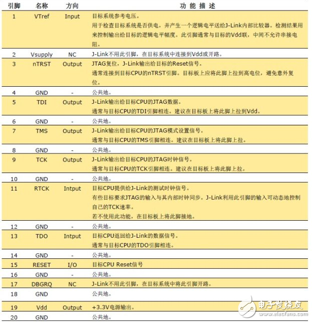
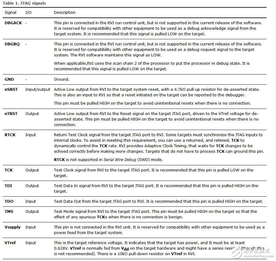
JTAG various interface pin definitions, meaning one, pin definition