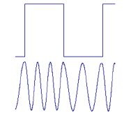
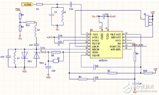
As an emerging high-performance serial communication technology, optical fiber communication has been gradually applied in the power field. Most of the current fiber-optic communication modules use FPGA or DSP technology to realize signal demodulation. Although the transmission speed is fast and the efficiency is high, the cost is high and the technology is complicated. Moreover, the transmission distance, electrical isolation characteristics, reliability, and product cost parameters are all included. Extremely high requirements. The application of optical fiber to the power industry is mainly focused on the control of high-voltage power. The on-site environment requires lower communication speed of the optical fiber module. Therefore, in the engineering practice of power systems, the application of high-cost high-speed fiber-optic communication technology is not very satisfactory due to the complicated on-site conditions and numerous interference signals. In view of the application status of optical fiber communication technology in power system, this paper proposes a low-speed fiber-optic communication module design scheme of MC3361+MCU structure. The hardware cost is low, the software flow is simple, and the performance is stable. The output signal is an industrial standard RS485 signal or RS232 signal, which can be directly connected to various power equipments, and is very suitable for wide use in power systems. Modulation principle The fiber-optic communication system is modulated by the MCU through the internal interface control through the PWM interface. The external device and the module are connected through a serial interface (including RS232 interface or RS485 interface). After receiving the data, the module first transmits the data to the MCU. The MCU receives the data through the UART interface, and the MCU outputs the BFSK modulated signal through the program control. The signal is sent directly to the fiber optic transmit interface for transmission. When performing BFSK modulation, the MCU serial interface is used to receive the data transmitted by the external device. The modulation frequency of BFSK is controlled by the program. The signal “1†corresponds to the 270KHz carrier frequency, and the signal “0†corresponds to the 240KHz carrier frequency. The waveform is shown in Figure 2. The upper waveform is an unmodulated signal, and the lower waveform is a modulated signal. The MCU sends the modulated carrier frequency signal to the fiber transmission interface through PWM, and the electrical signal is converted into an optical signal. The block diagram of the modulation hardware is shown in Figure 1. Figure 1 Modulation hardware block diagram Figure 2 Waveform of the signal before and after modulation Modulation and demodulation principle In order to reduce hardware costs and improve the reliability of hardware circuits, this design uses BFSK modulation and demodulation algorithms. The modulation principle of BFSK is to transmit digital messages by the frequency of the carrier, that is, to control the frequency of the carrier with the transmitted digital message. The BFSK signal is that the symbol "1" corresponds to the carrier frequency f1, and the symbol "0" corresponds to the modulated waveform of the carrier frequency f2 (another carrier frequency different from f1), and the change between f1 and f2 is instantaneously completed. . The demodulation of BFSK is done using the MC3361 single-chip narrow-band FM receiver chip. The MC3361 includes an oscillator circuit, a mixer circuit, a limiting amplifier, an integrating discriminator, a filter, a suppressor, a scan controller, and a squelch switch circuit. The schematic diagram of the demodulation circuit is shown in Figure 3. Among them, 185K network label is MCU output 185K rectangular wave signal, R1 is current limiting resistor, C5, L4 form filter circuit, C12 resonant capacitor, after signal passes R1, C5, L4 and C12, input by MC3361 pin 1 to form MC3361 Demodulated second local oscillator level. In Figure 3, the FSK network is labeled as a rectangular wave signal input from the fiber receiving interface. The signal is divided by R4 and R6 to convert the signal high level to 500mV, then filtered by L6 and C25, and C27, L7, VD1 and VD2. After the secondary voltage-limiting filtering, after eliminating the interference frequency, after C1 resonance, the final signal is converted into a sine wave signal. Figure 3 Schematic diagram of the demodulation circuit Finally, only the standard sine wave signal is input to the 16th pin of the MC3361 as the first intermediate frequency IF input signal of the MC3361. The signal amplitude is 0V, the peak value is 500mV, and the frequency is 270KHz or 230KHz. The second mixing stage inside the MC3361 is mixed. The processed signal is the second intermediate frequency signal of 455KHz. It is output by the third pin and selected by the 455kHz ceramic filter, that is, the Z4 device in Figure 3, and then Pin 5 is input to the MC3361's limiting amplifier for high gain amplification. The limiting amplifier stage is the main gain stage of the entire circuit. The 8th pin is connected to the frequency discrimination circuit, which is composed of 455kHz discriminators Z3, R2 and C26. The amplified second intermediate frequency signal is internally demodulated and demodulated, and amplified by the first audio voltage and output by the 9th pin. The signal and signal pass through the active filter circuit formed by pins 10 and 11 and then input to the 12th pin of MC3361 for carrier frequency detection and control of the electronic switch. Finally, the demodulated signal is output from the 13th pin and directly input to the MCU. The pin is processed by the MCU. Edit Comment : Fiber optic communication module FPGA or DSP technology to achieve signal demodulation, high cost, complex technology, using MC3361 + MCU structure of low-speed fiber optic communication module design, low cost, simple software flow, stable performance, and support RS485 signal or RS232 Signals, as well as power line connections, are ideal for promotion. Ebike Charger,Electric Motorcycles Chargers,E-Motorcycle High Power Charger,Electric Motorcycles Fast Charger HuiZhou Superpower Technology Co.,Ltd. , https://www.spchargers.com