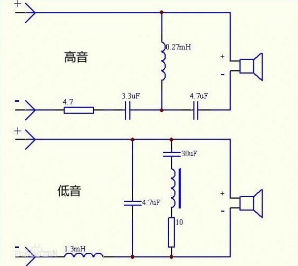
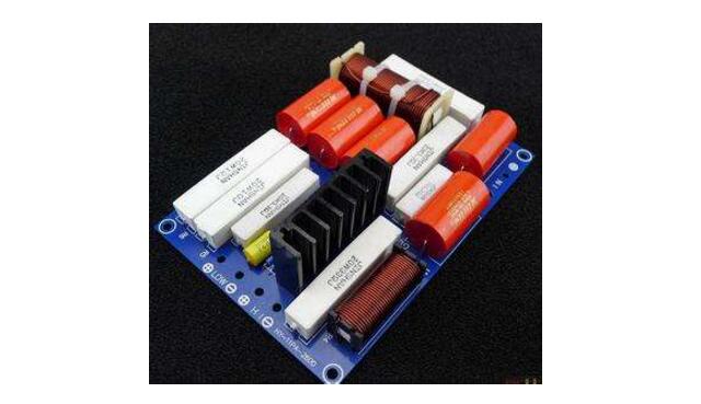
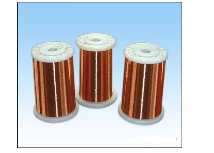
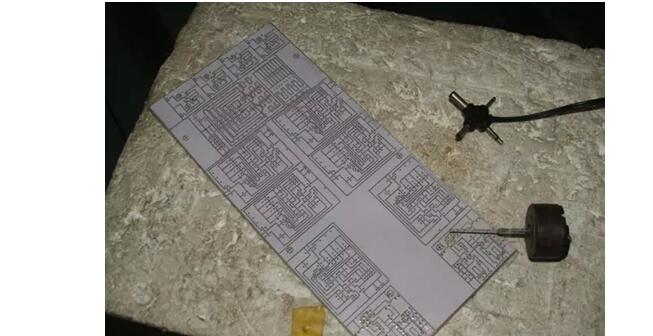
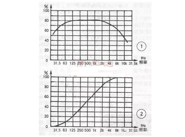
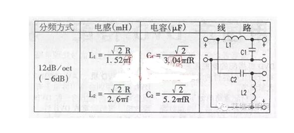
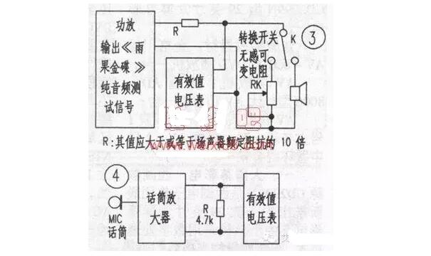
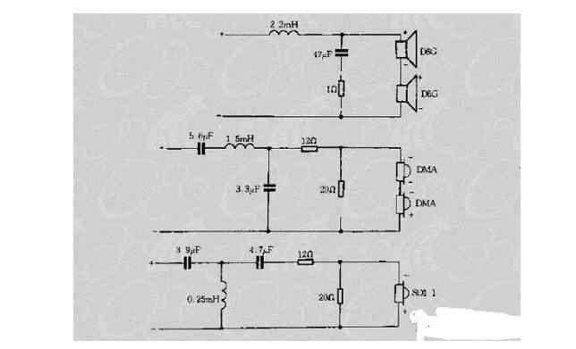
The speaker divider can divide the sound signal into several frequency bands. For example, the two-divider consists of a high-pass filter and a low-pass filter. A divide-by-three adds another band-pass filter. The divider is the "brain" in the speaker and is crucial to the sound quality. The use of frequency dividers The audio frequency divider is an audio device that divides the sound signal into several frequency bands. We know that the frequency range of the sound is between 20Hz and 20kHz. We hope to use only one speaker to ensure that a wide frequency sound such as 20Hz-20kHz is difficult to achieve, because it will be technically different. A variety of problems and difficulties. Therefore, under normal circumstances, high-quality playback systems, in order to ensure the frequency response and bandwidth of the reproduced sound, in the professional context, most of the high-bass and low-range amps are played, and when high-bass detached speakers are used to deliver sounds, It is necessary to use a divider. The speaker divider uses the following structure to analyze: The circuit that connects the tweeter: let the current flow through the capacitor first, stop the low frequency, let the high frequency pass, and the horn is connected in parallel with a coil, so that the coil generates a negative voltage, then this voltage is just a voltage compensation for the tweeter, so you can Restores sound current approximately realistically. Connecting the woofer circuit: current flows through the coil first, so that the high frequency part is blocked, and the low frequency band passes smoothly because the coil has no obstruction. Similarly, the woofer is connected in parallel with a capacitor, which is to use a capacitor to generate a high frequency. The voltage to compensate for the loss of voltage is the same as that of the tweeter. It can be seen that the characteristics of the capacitors and coils used by the frequency divider are frequency-divided. However, coils and capacitors eventually consume voltage in their respective blocking frequency bands, so the circuit divider will lose a certain amount of sound, and there are many compensation measures. Because the author has insufficient knowledge, it is difficult to say clearly. The electronic frequency division solves this problem. When the sound is input to the power amplifier, it is first divided, and then a dedicated amplification circuit is used to amplify the different frequency bands. In this case, the sound distortion is small and the restoration is realistic. But the circuit is complicated and expensive. The frequency divider is the "brain" in the speaker, and it is very important for the quality of the sound. The frequency divider is a kind of circuit device inside the speaker, which can separate the input music signal into different parts such as high, mid and bass. Then they are sent to the corresponding high, medium and bass speaker units for playback. The frequency divider refers to differentiating the sound signals of different frequency bands, respectively giving amplification, and then sending them to the speakers of the corresponding frequency bands for replay. In high-quality sound reproduction, electronic crossover processing is required. Whether it is a tweeter or a bass unit, their own frequency response curves are not flat, and both high and subwoofers are attenuated at both ends. The on-line attenuation of the ringing may coincide with the lower-limit attenuation part of the high-frequency audio, even overlapping, resulting in overlapping of the frequency bands and the inability to form a flat curve, so that the resulting sound will not be a good sound quality. The role of the divider is to complete the combination of these frequencies in each speaker to achieve better results. The frequency divider passes the music signal output by the amplifier through the filtered wave originals to allow the specific frequency signals of each unit to pass. In simple terms, the original signal is divided into several frequency bands, and the frequency divider selects the most suitable for the corresponding unit. The frequency band is assigned to it to achieve multi-speaker cooperation. 1, the inductor skeleton According to the requirement of the inductor coil, choose the appropriate non-metal skeleton, such as solder wire, plastic skeleton with sealed raw material tape, and other wood and resin skeletons. 2, enameled wire Choose a number of enameled wire with suitable thickness and good quality. 3, resistance and capacitance According to the circuit requirements, choose capacitors, resistors and capacitors with appropriate capacity, resistance and power. The best frequency divider capacitor is CB capacitor imported or made in China. The resistance of the resistor is high-power cement resistor. 4, adhesive This agent can use commercially available "vertical defense" and other strong viscosity adhesive. 5, coins, bolts The diameter of the brass with a diameter of about 4mm is selected for the bolt, and its length is determined by the height of the inductor skeleton. 6, copper plate According to the number of frequency-divided components, choose a good-quality copper-clad board of the right size, and the route direction will be carved with a utility knife according to the design requirements. 7, a transparent tape 1, around the inductor A top of the adhesive bottle, the middle of the bottom of each drilled a hole slightly larger than the diameter of the enameled wire (due to liquid viscosity, it will not flow out of the hole), in the two holes after wearing a plastic hose, the enameled wire from the two hose Pass through to ensure that the wire passes through the two holes and is not scratched. Then one person pulls one end of the enameled wire tight. The other person can take the other end of the enameled wire and wind it on the skeleton. When the hand is wound, the hands cannot touch the enameled wire. When the mixture has been evenly coated with a layer of adhesive, you can use both hands to hold the ends of the frame to rotate. After the number of inductor turns around, cut off the excess enameled wire, and fix the outer leads. After the adhesive had solidified, several layers were wrapped around the coil with clear tape. 2, component installation According to the position of the inductor coil and the resistor and capacitor on the board, a small drill is used to make a hole in the board. A hole slightly larger than the diameter of the copper bolt is drilled in the middle of the coin, and the copper bolt is passed through the coin, the coil and the circuit board in turn. Then put on the spring washer, fasten with the nut, scrape the lead of the coil, capacitor and resistance on the tin and solder it in the corresponding position, and finally weld the wire in and out on the board. After the above operation, a high-quality and inexpensive crossover device is completed and the rest is the joy of experiencing the success. Divider inductance wiring with stress The connection of the inductor coil in the speaker divider has a great influence on the sound quality. The use of a pair of inverted speakers, inductor coil connection is the outer ring into the ring sound balanced round. Used to enter the outer ring out of the connection method, the result is no bass. High-fidelity speakers are mostly composed of two or more speaker units. To restore high-quality audio signals from 20Hz to 20kHz in full-band, high frequency dividers must be used. Because the speaker units of the respective speakers are different, the frequency divider cannot be simply replaced, and must be manufactured in accordance with the characteristics of the specific speaker unit. Summarizes a relatively complete set of design, production, and debugging methods. It only requires the producer to have a “Hugo Gold Disc†containing a 20Hz to 20kHz pure audio test signal, a microphone signal amplifier, a microphone, and a number. Multimeter without special test equipment. Amateur production of speakers, it is recommended to choose two ways. 1, the choice of crossover frequency f The crossover frequency of two-way speakers can be optimized between 2 and 5kHz. Generally, the frequency f of the frequency divider is selected to be one octave below the upper limit of the bass unit, and the frequency range of the tweeter is one octave or more from the lower limit. 2, the divider and power distribution The high and bass units that make up the speaker have different nominal powers. In the power spectrum of the actual program signal, the proportions of the high-frequency and low-frequency signals are not the same, so after averaging the various signals, The analog signal power spectrum shown in FIG. 1 is obtained. The power spectrum of Figure 1 is calculated to obtain the power distribution curve shown in Figure 2. When selecting crossover points, it is necessary to consider the issue of power allocation so that the tweeter has a certain margin. Fig. 2 shows that the total power of 20 Hz to 20 kHz is normalized to 100%, and the power occupied by 20 Hz to a certain frequency f is the percentage of the total power. The application example is as follows. For a two-way system with a 25 kHz frequency division point, intersect the curve from the horizontal axis of 25 kHz to the curve in Figure 2 and read the percentage from the ordinate. Then, the power ratio from 20 Hz to 2.5 kHz is 87%, and the power ratio from 25 kHz to 20 kHz is 13%. When the total power is 100W, the bass power W is low=100&Times; 87%=87W, and the treble power W is high=100&Times; 13%=13W. When using the above power distribution relationship, please also pay attention to the power standard of the speaker unit. The general product label is rated maximum sine power (RMS), and some manufacturers mark the peak power or music power for commercial purposes, but the value is generally 2 to 4 times the RMS power. 3, the choice of frequency mode Although there are 6dB/oct type, 18dB/oct type, 3dB drop point crossing type, 12dB/oct type, 6dB drop point crossing type, etc., the frequency division method is 12dB/oct type, considering their advantages and disadvantages. 4, crossover network When designing a crossover network, it is of course best to add the load cell to the Rc impedance compensation circuit as a constant impedance design. However, after consulting a large number of books and materials, I found that there are many calculation methods for the Rc impedance compensation circuit, and the resulting RC values ​​are not the same, making it difficult to choose, and they have to be designed according to the frequency point resistance method. First, connect the circuit shown in Figure 3 to measure the resistance of the high and bass units at the crossover points (be careful not to replace them with the unit nominal impedance, otherwise the error will be very large), and then perform the calculations and presses in the upper right table. The figure connects the LC components and is ready for initial production. The sensitivity of the high and bass units is unbalanced. Resistor attenuation can be used to adjust. During manufacture, high-quality polypropylene capacitors are recommended. Air-core inductors are optimally designed. The components are fixed on printed boards with hot-melt adhesives. The inductors can be used with cotton or plastic buckles. Strengthen the fixation, connect with the method of scaffolding welding, and make the splitting and splitting of the high and bass channels independently. Self-made frequency divider adjustment method After experiment, according to the divider design, the principles of constant impedance method are used. The standard impedance is used instead of the speaker to debug the crossover network so that it meets the standard attenuation slope, and then the resistance is removed and the speaker is connected. In addition, the impedance correction network plus the re-tuning method was successful, and the actual audition sounded good. The figure below is the schematic diagram of the divider, for your reference;
Sports can't be abandoned more freely
Professional sound engineering technology
Bluetooth In Ear Headset,Wireless In Ear Headset,In Ear Headset Wireless,Headset Wireless In Ear Guangzhou HangDeng Tech Co. Ltd , http://www.hangdengtech.com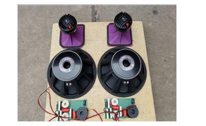

Close ergonomic design, close to the ear, even wearing for a long time can also enjoy comfortable experience.
And can form a triangular stable support with the ear, even if running and riding, vigorous fitness is still close to the ears, wildly shake off.
customized stainless steel acoustic structure, high quality grahene hoop system and obvious environmental noise attenuation will open up a pleasant journmey journey for you to enjoy the sound.
Built-in microphone/ Effective noise reduction/ Clear call/ Easy to carry
Speaker divider concept