With the rapid development of modern technology, the types of electrical and electronic equipment are constantly increasing, making the electromagnetic environment increasingly complex. In a complex electromagnetic environment, whether various devices or systems can work properly has become an urgent problem to be solved. As an important part of various devices or systems, the switching power supply is both a source of harassment and an interferer. High-power switching power supplies are often sources of harassment. When various switching power supplies work, they often produce some useful or useless electromagnetic energy. These electromagnetic energy will affect the normal operation of other equipment or systems. This is electromagnetic disturbance. Electromagnetic disturbances may degrade the operating performance of the switching power supply, even shorten the service life of the switching power supply, or may not work at all. It can be seen that electromagnetic compatibility design is very important and indispensable in switching power supplies. In switching power supply, the purpose of electromagnetic compatibility design is to make the switching power supply achieve electromagnetic compatibility in the expected electromagnetic environment. The requirement is to make the switching power supply meet the requirements of the relevant EMC standards and have the following two capabilities: 1 can be expected Normal work in the electromagnetic environment, no performance degradation or failure; 2 no pollution to the electromagnetic environment. 1 Several important concepts about electromagnetic compatibility 1.1 Electromagnetic environment Electromagnetic Aging Environment (Electromagnetic Tic Environment) refers to the distribution of power or time in the radiated or conducted electromagnetic emission levels in different frequency ranges that a device or system may encounter during normal operation. 1.2 Electromagnetic disturbance Electromagnetic Agitation (EMC) is any electromagnetic phenomenon that may cause the performance of a device, device, or system to be degraded, or that may cause damage to living or inanimate objects. Electromagnetic harassment is a kind of physical phenomenon that exists objectively. The reason may be external factors, or it may be its own changes. Electromagnetic harassment can be divided into natural harassment and human harassment according to its source. Natural harassment is characterized by its uncontrollable sources of origin, such as electronic noise, electrical noise, extraterrestrial noise, and depositional static electricity. Human harassment is characterized by its occurrence and controllability. For example: high-frequency and microwave equipment, high-voltage equipment, switchgear, spark equipment, nuclear electromagnetic pulse and so on. 1.3 Electromagnetic interference Electromagnetic Agile Interference (EMI) refers to the degradation of equipment, transmission channels, or system performance caused by electromagnetic disturbances. Electromagnetic interference is a consequence of electromagnetic disturbances. Electromagnetic interference may be caused by a useful electromagnetic signal from another device or system, or it may be some kind of electromagnetic noise. Electromagnetic Agile Compatibility (EMC) refers to the ability of a device, device, or system to function in the electromagnetic environment in which it is located, without any unacceptable electromagnetic harassment to the environment. According to the above definition, electromagnetic compatibility includes the following two aspects: 1.4.1 The equipment or system should have the ability to resist given electromagnetic disturbances That is, it should not be subject to electromagnetic disturbances emitted by its equipment or systems in the same electromagnetic environment, resulting in impermissible performance degradation. 1.4.2 The equipment or system does not produce electromagnetic disturbances exceeding the prescribed limits That is, it does not produce electromagnetic disturbances that degrade the performance of other devices or systems that are in the same electromagnetic environment beyond a specified limit. 2 General Approach to the Transmission of Electromagnetic Harassment There are two ways to transfer electromagnetic energy from the source of interference to the object of interference: conduction and radiation. From the receiver's point of view, coupling can be divided into two categories: conductive coupling and radiation coupling. Conductive coupling is divided into direct conductive coupling, common impedance coupling and transfer impedance coupling. Radiation coupling is divided into field (antenna)-to-antenna coupling, field-to-cable coupling, and cable-to-cable coupling. In the actual situation, conductive coupling and radiation coupling are not totally different. They can be transformed into each other. For example, when the current conducted in the metal conductive line is large, the radiation can be severe. 3 Electromagnetic Compatibility Design of Switching Power Supply According to the transmission route of electromagnetic disturbance, the electromagnetic compatibility design of the switching power supply includes: perfect circuit design, grounding design, filter design, and shield design. 3.1 Improve circuit design The topology of the selected switching power supply should not generate excessive voltage and excessive current to avoid high voltage electric field interference and large current magnetic field interference. When the requirements are met, the amplifier's frequency band is as narrow as possible, making it less susceptible to interference. Appropriately increase the buffer circuit. When designing a printed circuit board, the following points should be noted: 1 When high, medium, and low speed logic circuits are used at the same time, high speed should be designed at the entrance of the circuit board; 2 signal input plus RC decoupling filter to eliminate long-term transmission interference; 3 circuits The current loop should be kept to a minimum; 4 signal lines and loops should be as close as possible; 5 use a larger ground plane to reduce ground impedance; 6 power and ground lines should be close to each other; 7 in a multilayer circuit board , Should separate the power supply plane and the ground plane; 8 arc wiring, not abrupt changes; 9 as short as possible to reduce the connection; 10 analog circuits and digital circuits are separated, power circuits and control circuits are separated. 3.2 Grounding Design Grounding is an important method for suppressing electromagnetic noise in switching power supply equipment. The role of grounding: 1 to improve the stability of the system work, if not connected with the earth, susceptible to interference from the ground capacitance; 2 discharge electrostatic induction static electricity in the chassis, to avoid high voltage discharge; 3 operational safety. Regardless of the safety grounding, only from the perspective of the circuit reference point, the grounding can be divided into floating ground, single-point grounding, multi-point grounding and mixed grounding. Floating ground: Separating the reference ground in the switching power supply from the chassis can prevent the interference current in the chassis from directly coupling into the power supply circuit. When the floating system is close to high pressure, electrostatic charges may accumulate to form a hazard, or electrostatic discharge may be caused and an interference current may be formed. In a lightning environment, an arc occurs between the chassis and the unit circuit. Therefore, floating power should not be used in switching power supplies. Single-point grounding: It is divided into single-point series grounding and single-point grounding. The advantage of single-point series grounding is relatively simple. The disadvantage is that each circuit will affect each other through the grounding wire. When using this grounding method, care must be taken to place the highest level circuit at A closest to the grounding point to minimize the potential rise at points B and C. Compared to a single point series grounding, there is no common ground impedance interference for a single point of parallel connection, but the number of ground lines is large, and the effect is poor at high frequencies (MHz or more). Multi-point grounding: Each grounding point is grounded nearby, which has the advantages of simple wiring, short lead length, and high frequency standing wave phenomenon. The disadvantage is that the ground impedance increases with increasing frequency. Hybrid grounding: The actual situation is more complex and it is difficult to solve it by only a simple grounding method. Instead, single-point grounding and multi-point grounding are often combined to form a hybrid ground. 3.3 Filter Design Filtering is a frequently used measure to eliminate interference. In the design and selection of filters should pay attention to the following questions: 1 clear the operating frequency and the interference frequency to be suppressed, if the two are very close, you need to apply very steep frequency filter, in order to separate the two frequencies; 2 Ensure that the filter can work reliably under high voltage conditions; 3 when the filter is continuously connected to the maximum rated current, the temperature rise is low to ensure that the working performance of the device in the filter is not damaged when the rated current is continuously operated; 4 In order to make the frequency characteristic of the filter during operation accord with the design value, the value of impedance and load impedance of the signal source connected with it must be equal to the design value; 5 the filter must have a shield structure, and the shield cover and the body must have For good electrical contact, the capacitor lead of the filter should be as short as possible, and the lead-through capacitor with low lead short inductance is preferred. When installing the filter, the following points should be noted: 1 The power line filter should be installed as close as possible to the power supply inlet of the device. Do not allow the unfiltered power cable to bypass the device frame. 2 The capacitor leads in the filter should be Keep it as short as possible so as not to cause resonance at lower frequencies due to lead inductance and capacitive reactance; 3 large short-circuit current through the grounding conductor of the filter will cause additional electromagnetic radiation, so the filter element itself should be well Shielding and grounding processing; 4 The input and output lines of the filter cannot be crossed, otherwise crosstalk may be caused by the input-output capacitive coupling path of the filter, thereby reducing the filtering characteristics. The usual method is to add a separator between the input and output ends or Shield. 3.4 Shield Design Shielding has two purposes. One is to limit the internal electromagnetic radiation energy from leaking out of the inner zone, and the other is to prevent external radiation interference from entering the inner zone. The principle of electromagnetic shielding is to use the shielding body to reflect, absorb and guide the electromagnetic energy flow, and these effects are closely related to the charge, current and polarization induced on the surface of the shielding structure and in the shielding body. The design principle of the shield: 1 first determine the electromagnetic environment, including the type of electromagnetic field, the field strength, frequency and the distance from the shield to the source, etc.; 2 determine the sensitivity of the receiver and the shielding requirements of the shield; 3 according to electromagnetic shielding The requirements and the nature of the electromagnetic field, the appropriate choice of material conductivity, permeability and thickness; 4 after the determination of the shielding material, the shielding structure design, the main choice for the electric field shielding high conductivity materials (such as copper), for the magnetic shielding , Especially low-frequency magnetic field shielding; mainly choose iron or other high permeability materials. If the requirements are not met, under the permitted conditions, the method of increasing the thickness can be used; 5 If the single-layer shielding can not meet the requirements of the shielding, more than two layers of shielding can be used to obtain better shielding effect; 6 When the shielding room needs When it is transparent, metal mesh shielding can be used. The performance of metal mesh shielding is obviously inferior to that of metal solid wall shielding. Therefore, double-layer shielding is generally used; 7 For the ventilation hole, the opening shielding shell of the detector, the cable inlet and outlet connectors, etc. The openings are designed according to special requirements.
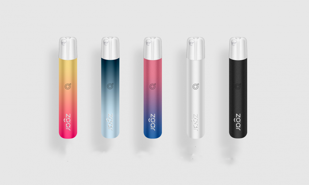
Zgar 2021's latest electronic cigarette Aurora series uses high-tech temperature control, food grade disposable pod device and high-quality material.Compared with the old model, The smoke of the Aurora series is more delicate and the taste is more realistic ,bigger battery capacity and longer battery life. And it's smaller and more exquisite. A new design of gradient our disposable vape is impressive. We equipped with breathing lights in the vape pen and pod, you will become the most eye-catching person in the party with our atomizer device vape.
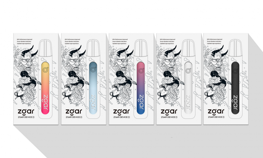
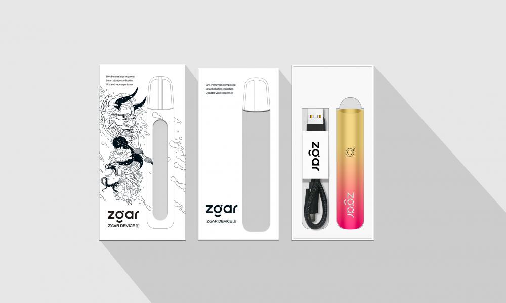
The 2021 Aurora series has upgraded the magnetic suction connection, plug and use. We also upgrade to type-C interface for charging faster. We have developed various flavors for Aurora series, Aurora E-cigarette Cartridge is loved by the majority of consumers for its gorgeous and changeable color changes, especially at night or in the dark. Up to 10 flavors provide consumers with more choices. What's more, a set of talking packaging is specially designed for it, which makes it more interesting in all kinds of scenes. Our vape pen and pod are matched with all the brands on the market. You can use other brand's vape pen with our vape pod. Aurora series, the first choice for professional users!
We offer low price, high quality Disposable E-Cigarette Vape Pen,Electronic Cigarettes Empty Vape Pen, E-cigarette Cartridge,Disposable Vape,E-cigarette Accessories,Disposable Vape Pen,Disposable Pod device,Vape Pods OEM vape pen,OEM electronic cigarette OEM e-cigarette OEM e-cig to all over the world.
E-Cigarette Vape Pen,Disposable Device Vape,Vape Pen Atomizer,Latest Disposable E-Cigarette OEM vape pen,OEM electronic cigarette ZGAR INTERNATIONAL(HK)CO., LIMITED , https://www.zgarvapepen.com
ZGARVAPE
