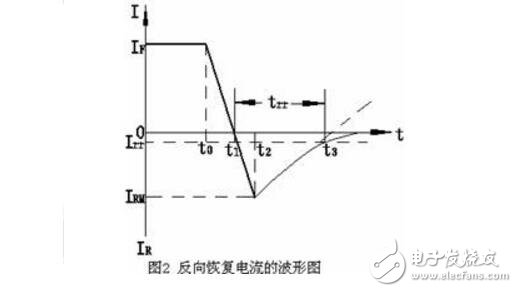
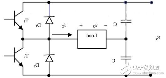
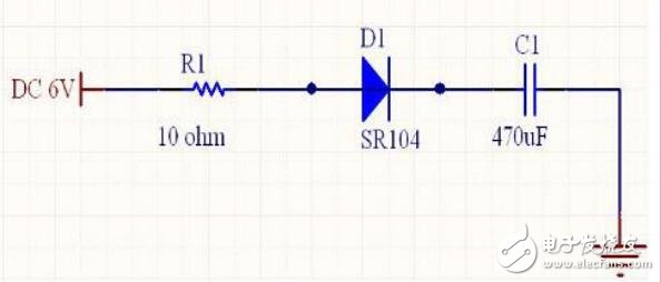
Fast recovery diode (FRD for short) is a semiconductor diode with good switching characteristics and short reverse recovery time. It is mainly used in electronic circuits such as switching power supplies, PWM pulse width modulators, frequency converters, etc., as high-frequency rectifier diodes, Freewheeling diode or damping diode is used. Fast recovery diodes adopt gold-doped and pure diffusion processes in the manufacturing process to obtain higher switching speeds and higher withstand voltages. At present, fast recovery diodes are mainly used as rectifier components in inverter power supplies. The internal structure of the fast recovery diode is different from the ordinary PN junction diode. It belongs to the PIN junction diode, that is, the base area I is added between the P-type silicon material and the N-type silicon material to form a PIN silicon chip. Because the main active area of ​​the PD is the barrier area, the sensitivity can be improved by widening the barrier area. The pin junction fast recovery diode is actually to artificially expand the width of the barrier region of the pn junction, that is, use a wider intrinsic semiconductor (i) layer to replace the barrier region, and become a pin junction. The effective area of ​​the pin junction fast recovery diode is mainly the i-type layer (barrier area) with electric field, the effective area for generating photo-generated carriers is enlarged, the influence of diffusion is weakened, and the junction capacitance is also greatly reduced. Therefore, the sensitivity and response speed of light detection have been greatly improved. The internal structure of the fast recovery diode is to increase the base area I between the P-type silicon material and the N-type silicon material to form a PIN silicon wafer. Because the base area is very thin, the reverse recovery charge is very small, which not only greatly reduces the TRR value, but also reduces the transient forward voltage drop, so that the tube can withstand a high reverse working voltage. The reverse recovery time of fast recovery diodes is generally several hundred nanoseconds, the forward voltage drop is about 0.6V, the forward current is several amperes to several thousand amperes, and the reverse peak voltage can reach several hundred to several thousand volts. The reverse recovery charge of the ultrafast recovery diode is further reduced, making its trr as low as tens of nanoseconds. Most of the fast recovery and ultra fast recovery diodes below 20A are in TO-220 package. When a negative voltage (or zero bias) is applied, the fast recovery diode is equivalent to a capacitor + resistance; when a positive voltage is applied, the fast recovery diode is equivalent to a small resistance. By changing the structure size and selecting the parameters of the fast recovery diode, the reflection phase (reference phase) of the short-circuited stepped ridge waveguide is the same as the reflection phase of the short-circuited waveguide controlled by the PIN tube with positive voltage. It is also required that the reflection phase of the short-circuit waveguide controlled by a fast recovery diode with a negative voltage (or 0 bias) is opposite to the standard phase (between -164° and +164°). The main feature of the fast recovery diode is that its reverse recovery time (trr) is below several hundred nanoseconds (ns), and the ultrafast recovery diode can even reach tens of nanoseconds. The figure is a waveform diagram of reverse recovery current. In the figure, IF is the forward current, IRM is the maximum reverse recovery current, Irr is the reverse recovery current, and Irr=0.1IRM is usually specified. When t≤t0, the forward current I=IF. When t>t0, because the forward voltage on the rectifier tube suddenly becomes a reverse voltage, the forward current decreases rapidly. At t=t1, I=0. Then the reverse current IR on the rectifier tube gradually increases; the maximum reverse recovery current IRM value is reached at t=t2. After that, under the action of the forward voltage, the reverse current gradually decreases and reaches the specified value Irr at t=t3. The reverse recovery process from t2 to t3 is similar to the capacitor discharge process. The time interval from t1 to t3 is the reverse recovery time trr. The fast recovery diode has the characteristics of high withstand voltage and low leakage current during reverse blocking, and low on-state resistance and large current in the forward direction. Because it is used as a switch, it is generally required to switch quickly. In addition, proper selection of the characteristics of the freewheeling diode, especially the reverse recovery characteristics, such as reverse recovery time and reverse recovery softness, can significantly reduce the power consumption of switching devices, diodes and other circuit components, and reduce the The voltage spike and electromagnetic interference caused by the diode can minimize or even remove the absorption circuit. Generally speaking, the forward voltage drop of the fast recovery diode is small, about 0.4V, while the ordinary silicon tube is about 0.6V. In order to reduce the loss, the fast recovery diode is used. If the reverse breakdown voltage of the fast recovery diode is 40V, it can recover quickly after the reverse breakdown; if the reverse breakdown voltage of the fast recovery diode is 1000V, there is no reverse breakdown problem, so this is true in the DC circuit No need to consider. 4G Module,4G Router Module,4G Wifi Module,4G Lte Wifi Module Shenzhen MovingComm Technology Co., Ltd. , https://www.movingcommiot.com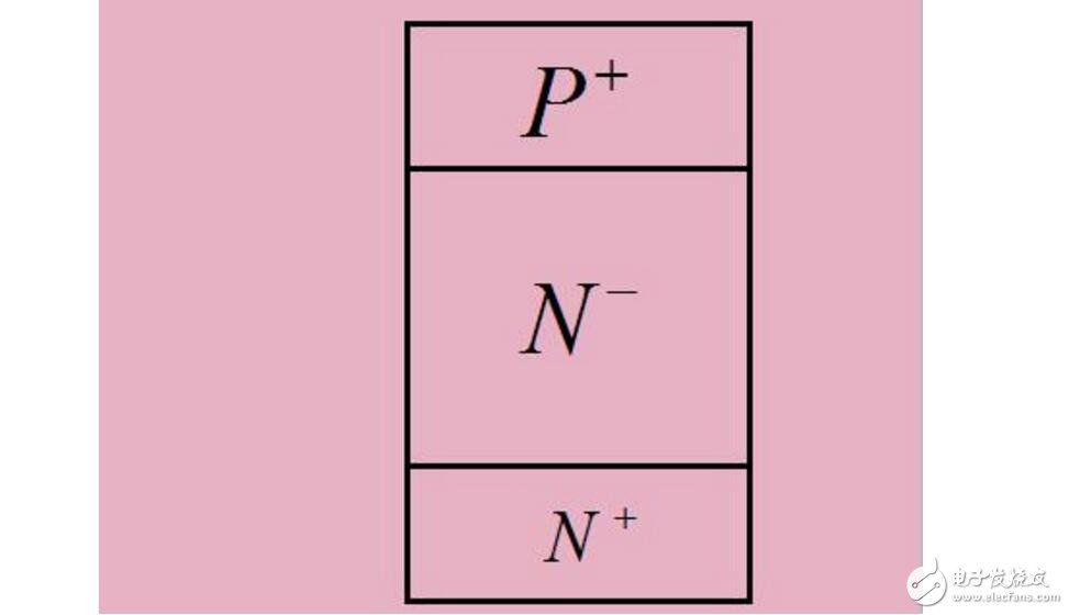
var videos %2F2017-05-11T09%3A02%3A31Z%2F-1%2F%2F16a5afab61e03efe14b2714eb74f88eb608635186d8f7a14eb798baab28df18c" }; if (!! window.ActiveXObject) {videoObject.html5m3u8 = false} var video playerObject = new ckplayer(Object); quick recovery diode overview