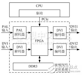
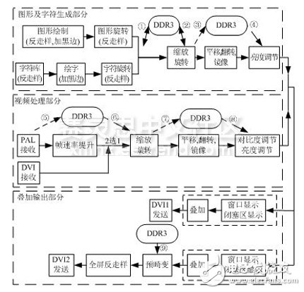
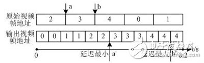
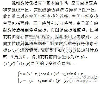
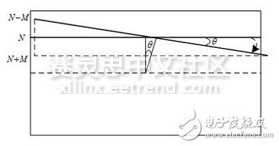
This paper designs and optimizes the architecture of the on-board video graphics display system based on FPGA. From real-time, BRAM resource occupancy and DDR3 throughput, the frame rate improvement algorithm is improved to improve real-time performance; the video rotation algorithm is improved to reduce BRAM resource usage; and the order of different modules is changed to reduce the throughput of DDR3. The results show that the designed system architecture meets the performance requirements; by comparing the systems before and after optimization, the real-time performance is better, the BRAM resource usage is reduced, the DDR3 throughput is reduced, and the overall performance is improved. With the continuous development of avionics technology, modern on-board video graphics display systems are increasingly demanding performance such as real-time performance. There are three main types of common system architectures: (1) Based on the architecture of GSP+VRAM+ASIC [1], the advantage is that the graphic ASIC can effectively improve the quality and speed of graphic display. The disadvantage is that the cost of complex ASIC design in China is extremely high and the process is not mature. (2) Based on DSP+FPGA architecture [2], the advantage is that the DSP has a unique advantage of algorithm analysis and FPGA parallel execution of data stream, and the performance of graphics processing is improved. The disadvantage is that the upper CPU side will openGL drawing function. After being packaged, it is sent to the DSP. After the DSP is split, the FPGA is called. The integration degree of the system is not high, and the interface design is complicated. (3) FPGA-based SOPC architecture [3], the advantage is that the integration is very high; the disadvantage is that the logic and CPU are integrated, which is not conducive to development. After comparison, the architecture design of the on-board video graphics display system has optimization space, which deserves further research to design a more real-time solution. This paper designs an FPGA-based graphics generation and video processing system, which can realize 2D graphics and character rendering, form various flight parameter images, and superimpose external video images. While ensuring display quality, it is optimized to further improve real-time performance, reduce the use of internal BRAM, and reduce the throughput of DDR3. The overall design of the system is shown in Figure 1. With Xilinx's Kintex-7 FPGA as the core, a real-time airborne video graphics display system is built. The upper CPU receives graphics and video control commands from systems such as flight control and navigation. After formatting and preprocessing the data, it is transmitted to the FPGA through the PCIe interface. This paper is mainly to design and optimize the internal logic module of FPGA. Figure 1 Overall design block diagram of the airborne display system The onboard display system design mainly includes 2D drawing, video processing and superimposed output. 2D drawing capabilities include the rapid generation of lines, circles, characters, and more. Video processing functions include input video selection, video scaling, rotation, flipping, and more. The superimposed output function superimposes the video as a background and a graphic, and sends it to two DVI outputs. After one predistortion correction, one output is output to the flat display, and the other is directly output for ground recording. In order to meet the above functions, the overall flow chart of the FPGA logic design is shown in Figure 2. Figure 2 Overall flow chart of FPGA logic design Video processing requires both simple external video processing and post-superimposition video processing. Taking the rotation processing as an example, if the image is superimposed on the image after the simple external video rotation processing, and then superimposed and then rotated, the delay is very large. Therefore, in order to improve real-time performance, it is considered to rotate the entire image and the outer video separately, and then superimpose each other. The frame rate boost module has the largest latency throughout the process. 2.1.1 Frame Rate Boost Algorithm Frame rate boost refers to the interpolation of new image frames between original image frames. The common frame rate lifting algorithm [4] mainly includes frame copying method, frame averaging method and motion compensation method. Considering the display effect and real-time requirements, the frame copy method is finally selected. The frame copy method is easy to implement and has a low amount of calculation. Its expression is: Here, the input PAL video frame rate is 25 frames/second, and the output DVI video frame rate is 60 frames/second, that is, the 5-frame image is interpolated to 12 frames within 0.2s. As shown in Figure 3, DDR3 opens up 5 frames of storage space for storing 25 Hz original images, and inputs 5 frames of original images in 0.2 to output 12 frames of images. The delay is 1.5 to 2.6 frames of PAL, and the maximum delay is . Figure 3 frame rate improvement diagram The airborne display system designed in this paper uses a piece of DDR3 as the external memory, and all graphics and video data needs to be cached into DDR3. In order to resolve data storage conflicts, the data needs to be cached first into the internal BRAM. The XC7k410T has a total of 795 36Kb BRAM. Throughout the process, the largest use of BRAM resources is the graphic overall rotation and video rotation module. 2.2.1 Video rotation algorithm The advantage of the inverse rotation mapping is that the rotated coordinates are reversely rotated. In addition to the original coordinate range, the coordinates of the coordinates can be mapped to the floating point coordinates, and the coordinates of the coordinate neighborhood can be used to uniquely determine the coordinates. Pixel value, there will be no "hole" phenomenon. Figure 4 is a schematic diagram of the video rotation algorithm Power Breadboard,Breadboard Power Supply,Breadboard Power Supply Module,Breadboard Power Module Cixi Zhongyi Electronics Factory , https://www.cx-zhongyi.com