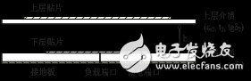
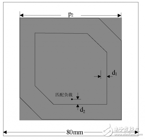
Microstrip antennas are widely used in various communication systems due to their low cost, low profile, small size, easy integration and conformality, and the convenience of linear polarization and circular polarization. Due to its simple and compact structure, the single-feedpoint circularly polarized microstrip antenna has attracted wide attention of researchers, but its design difficulty far exceeds that of linearly polarized microstrip antennas and multi-feedpoint circularly polarized microstrip antennas. Common single-feed point circularly polarized microstrip antennas mainly include slotted patches, square chamfer patches, quasi-square patches, and circular patches. Because their axial ratio is narrower, generally less than 3%, which seriously restricts the application of single-feedpoint circularly polarized microstrip antennas. In order to broaden the bandwidth of the microstrip antenna, a stacked microstrip structure is often used. The upper and lower radiating elements of the structure respectively correspond to two resonant frequencies. By adjusting the size and upper and lower spacing of the radiating patch, the two resonant bandwidths are closely adhered to form a bimodal resonance, which greatly expands the bandwidth of the microstrip antenna. Using a quasi-square laminated structure, more than 13% of the axial ratio bandwidth is obtained; Kwok Lun Chung et al. use a microstrip line-fed laminated square chamfer patch structure to obtain an 8% 3dB axial ratio bandwidth; The pin-bottom fed-fed laminated square-cut patch antenna achieved a 12.7% 3dB axial ratio bandwidth. In this paper, the square corner-cut patch can realize the position of two feed points with different directions of circular polarization, and one port is fed, one port is fed, and the other port is matched with impedance. The corresponding circular polarization mode is implemented by the feed port, and the impedance matching of the other port serves to reduce the height of the profile. In addition, the antenna of this paper adopts a structure in which two layers of square-cut microstrip patches are stacked, and a bimodal resonant circuit is formed to obtain a wider axial ratio bandwidth. The antenna structure is shown in Figure 1. It consists of two layers of square chamfer patches, an air layer and a ground plane. Lower dielectric: dielectric constant εr1, loss tangent tgδ1, thickness t1; upper dielectric: dielectric constant εr2, loss tangent tgδ2, thickness t2; air layer thickness h. Figure 1 Antenna structure Figure 2 shows the top view of the antenna and gives the size parameters of the patch, which are described as: the length of the lower patch p1, the depth of the chamfer q1; the length of the upper patch p2, the depth of the chamfer q2; the position of the two feed points Located on the center line of the lower patch, the feed port is located on the center line along the x direction, from the right edge d1; the matching load is located on the center line along the y direction, from the lower edge d2 of the lower layer patch. Figure 2 Antenna top view and size parameters The lower layer of the antenna was made of FR-4 substrate with t1 = 3 mm, εr1 = 4.4, and tgδ1 = 0.02; the upper layer was made of polytetrafluoroethylene sheet with t2 = 1.5 mm, εr2 = 2.55, and tgδ2 = 0.0011. The initial side length of the upper and lower patches is taken as: p1 = 42.6 mm, p2 = 71.4 mm. The calculation of the micro-wound quantities q1 and q2 of the upper and lower square patches. The HFSS software is used to repeatedly adjust the parameters of p1, p2, q1, q2, d1, d2, h, etc. to obtain the widest axial ratio bandwidth.
The electrolyte material inside the electrolytic capacitor, which has charge storage, is divided into positive and negative polarity, similar to the battery, and cannot be connected backwards.A metal substrate having an oxide film attached to a positive electrode and a negative electrode connected to an electrolyte (solid and non-solid) through a metal plate.
Nonpolar (dual polarity) electrolytic capacitor adopts double oxide film structure, similar to the two polar electrolytic capacitor after two connected to the cathode, the two electrodes of two metal plates respectively (both with oxide film), two groups of oxide film as the electrolyte in the middle.Polar electrolytic capacitors usually play the role of power filter, decoupling (like u), signal coupling, time constant setting and dc isolation in power circuit, medium frequency and low frequency circuit.Non-polar electrolytic capacitors are usually used in audio frequency divider circuit, television S correction circuit and starting circuit of single-phase motor.
Electrolytic Capacitor,Aluminum Electrolytic Capacitor,High Voltage Electrolytic Capacitor,12V Electronic Components Capacitor YANGZHOU POSITIONING TECH CO., LTD , https://www.yzpstcc.com