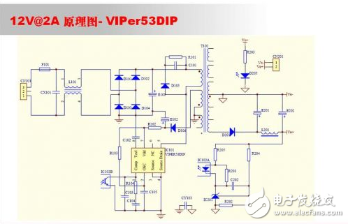
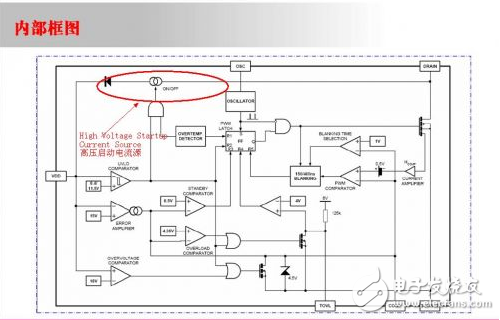
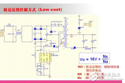
As a transformer engineer, you need those skills to get the job done right before you can play a role in this work chain. First, we must understand the role of the transformer in the circuit, and learn the voltage and current waveforms of the transformer when the circuit is working. Only by understanding this knowledge can it be possible to innovate some novel structures. Only by understanding these principles can we find a solution when the transformer is in use. In recent years, the development and application of power transformers has gradually shown professional characteristics. The design and production of low-power switching power supply transformers are more in line with civilian requirements. In today's solution sharing, we will share a low-power power transformer design and production process for engineers to learn from. The first step in the design of the switching power supply is to look at the specifications. Many people have contacted it; it can also be proposed for your reference. I will help with the analysis. I only bring you a 12V2A conventional isolated switching power supply with a wide range of inputs. 1. Determine the power first. According to the specific requirements, the corresponding topology is selected; such a switching power supply with multiple choices of flyback can basically meet the requirements. Note: I will choose more empirical formulas to calculate here. If there is any need for analysis, I can take it out and discuss it. 2. When we decided to design with the flyback topology, we need to select the corresponding PWM IC and MOS for the preliminary circuit schematic design (sch). Whether you choose to use discrete or integrated, you can consider it yourself. I will also break down the calculations inside. Discrete: PWM IC and MOS are separate, this advantage is that the power can be freely matched, the disadvantage is that the design and debugging cycle will be longer (only from the design point of view); Integrated: It integrates PWM IC and MOS in a single package, eliminating the need for many calculation and debugging steps by designers, suitable for just getting started or fast development environment. 3. After determining the selected chip, start making the schematic (sch). Here I chose ST VIPer53DIP (integrated with MOS) for design, why (because we are selling this chip)? Before designing, it is best to look at the corresponding datasheet and confirm the simple parameters yourself: Whether you choose PI integration, or separate 384x or OB LD, you need to refer to the datasheet. The general datasheet will be accompanied by a simple circuit schematic. These schematics are our design basis. 4. After we complete the schematic, we need to determine the corresponding parameters to enter the next PCB layout. Of course, different companies have different processes, we need to follow the corresponding process and develop a good design habit. This step may have preliminary evaluation, schematic confirmation, etc. After the signing is completed, it can be calculated. First attach the corresponding schematic There is no need to start the resistor because a high-voltage startup current source has been integrated into this film as shown below: Of course, for a chip that needs to start a resistor such as UC384X, if you calculate the resistance of the startup resistor, you can do this. Rstart = (Vin(min) - Vdd ) / Istart Rstart: Startup resistor Vin(min): Enter the minimum DC voltage Vdd: chip supply voltage Istart: chip startup current A very deep problem, but also the advantage of VIPl53 different from other single chip power R205 is disconnected or equivalent to the optocoupler is removed (equivalent to the secondary side loss feedback), the power supply will still work normally. At this time, enter the primary side feedback mode PSR, refer to the middle of the Vdd pin of the block diagram, which will be The first-order inertia link on the COMP pin forms a stable PWM control system The reference circuit diagram is as follows:
Rotary encoders are used as sensors for angle,position,speed and acceleration. We can offer incremental encoders and absolute encoders.
Absolute Encoder,Custom Encoder On Motor,Custom Optical Encoders,High Resolution Encoder Yuheng Optics Co., Ltd.(Changchun) , https://www.yuhengcoder.com