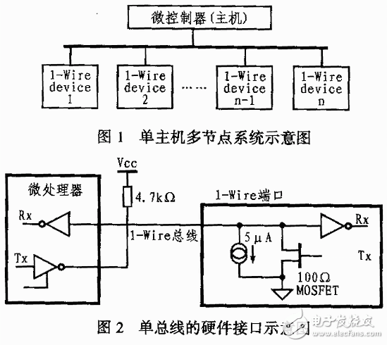
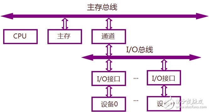
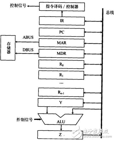
In many single-processor computers, a single system bus is used to connect the CPU, main memory, and I/O devices, called a single bus structure. At this point, the logic components connected to the bus must be running at high speed to get the bus control quickly when some devices need to use the bus; and when the bus is no longer used, the bus control can be quickly abandoned. A single bus master or slave device is connected to the data line through an open-drain or tri-state port, which allows the device to release the data bus when no data is being transmitted, allowing the device to release the bus when not transmitting data, leaving the device Use the bus. A single bus requires an external pull-up resistor of approximately 5 kΩ. Thus, when the single bus is idle, the state is high. If the transfer process needs to be temporarily suspended and the transfer process is required to continue, the bus must be idle. There is no limit to the recovery time between transfers as long as the bus is idle (high) during recovery. If the bus is held low for more than 480 us, all devices on the bus will be reset. In addition, in the parasitic mode power supply, in order to ensure that the single bus device has sufficient power supply current under certain operating conditions (such as temperature conversion device, EEPROM write, etc.), a strong pull-up must be provided on the bus. (1) Instruction fetch: When the CPU fetches an instruction, the address in the program counter PC is first sent to the bus along with the control information. The address in the case of "fetch instruction" is the main memory address, and the contents of the main memory unit specified by the address must be an instruction and will be transmitted to the CPU. (2) Transfer data: After the instruction is fetched, the CPU will check the operation code. The opcode specifies what action is to be performed on the data and whether the data flows into the CPU or out of the CPU. (3) I/O operation: if the instruction address field corresponds to the peripheral device address, the peripheral device decoder responds, so that data transfer occurs between the CPU and the peripheral device corresponding to the address, and the data transfer The direction is determined by the instruction opcode. (4) DMA operation: Some peripheral devices can also specify an address. If an address specified by a peripheral device corresponds to a main memory location, the main memory responds, so direct memory transfer (DMA) will occur between the main memory and the peripheral. (5) The single bus structure can be easily expanded into a multi-CPU system: this can be done by attaching multiple CPUs to the system bus.
The role of Bushing Cover : is the use of non-conductive material will be charged with isolation or wrapped up the characteristics of a safety measure to prevent electric shock. Good insulation to ensure the safe operation of electrical equipment and lines.
Applications:
1. Busbar Insulation Cover can Effectively eliminate short circuit accidents caused by small animals such as birds and animals or foreign body lap.
2. Prevent electrical accidents caused by condensation flash branding, dirty flash branding and icicle sticking to snow.
3. Bushing Covers can prevent acid rain, salt spray and harmful chemical gases from corrosion of transformer inlet and outlet lines.
4. Avoid casualties caused by pedestrians touching exposed electrical contacts by mistake.
5. The protective cover and metering device can be fully closed operation to prevent illegal elements stealing electricity.
6. Buckle structure, simple installation, reusable.
Bushing Cover,Busbar Insulation Cover,Cover Bushing,Bushing Covers CAS Applied Chemistry Materials Co.,Ltd. , https://www.casac1997.com

