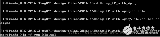
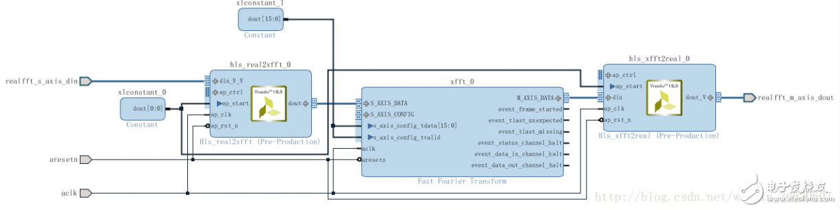
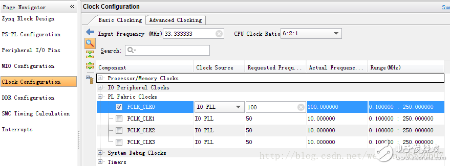
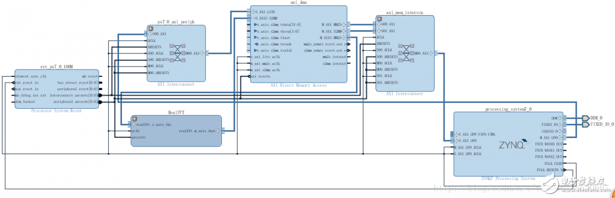
Overview For hardware acceleration modules, these hardware acceleration modules consume data originating from CPU memory and generate data in streaming mode. As used herein, Vivado HLS and xfft IP module (IP Integrator HLS IP in that section used). These modules are connected to the AXI4 slave port of HP0, allowing the data of the zynq7 processing system to pass through the AXI DMA IP core. The hardware acceleration module is free to run and does not require a driver, as long as the data is pushed by the CPU (often referred to simply as the processing system or PS). It is also important to emphasize the software requirements to avoid cache coherency issues. Streaming Data between Zynq CPU and HLS Acceleration Module Step 1: Generate HLS IP There are two Vivado HLS files, fe_vhls_prj and be_vhls_prj, which both contain the HLS IP. Step 2: Create the Vivado Project Open Vivado, select Create New Project, select the lab2 folder in Project locaTIon, name the project name project_1, then select RTL Project and do not specify sources at this TIme, select ZYNQ-7 ZC702 EvaluaTIon Board in Board. Finally click Finish. Step 3: Add HLS IP to IP Curry Click IP Catalog in the Flow Navigator window, then select IP SetTIngs, select Add Repository in the IP Settings dialog box, Create New Folder in lab2, and name it vivado_ip_repo, then add lab2/hls_designs/fe_vhls_prj/IPXACTExport/impl/ip and lab2 /hls_designs/be_vhls_prj/IPXACTExport/impl/ip, now there are two IPs Hls_real2xfft and Hls_xfft2real in HLS IP. Step 4: Create a top-level module design 1. Click Create Block Design and name it Zynq_RealFFT, then add Fast Fourier Transform IP, double-click IP to open Re-customize IP, set Transform Length to 512, Target Clock Frequency to 100 MHz, and select Pipelined, Streaming I/ O, then set Control Signals to ARESETN in the Implementation window, Output Ordering Options to Bit/Digit Reversed Order, and finally select Non Real Time, click OK 3. Add the pins to the RealFFT hierarchical block, double-click the RealFFT to open the block, right-click the din_V_V port of the hls_real2xfft_0 module, and select Create Interface Pin, and name it realfft_s_axis_din (other default), and give the ap_clk port Create Pin of the hls_real2xfft module. Named aclk, the same as the dout_V port Create Pin of the hls_xfft2real module, and named realfft_m_axis_dout, the same as the ap_res_n port Create Pin, and named aresetn. 4. Right-click Add IP input const, double-click xlconstant_0 module to confirm Const Val is set to 1, expand all ap_ctrl ports, connect all ap_start ports with xlconstant_0 output ports, then connect all aclk and aresetn ports respectively, add a new xlconstant Here, set the Const Width to 16, set Const Val to 0, expand the S_AXIS_CONFIG port, and finally connect s_axis_config_tdata and s_axis_config_tvalid with the new xlconstant module, as shown below. 5. Add ZYNQ7 Processing System IP, click Run Block Automation, then double-click processing_system7_0 module, click Presets, select ZC702 development board, then click PS-PL Configuration, expand HP Slave AXI Interface, select and confirm under S AXI HP0 interface S AXI HP0 DATA WIDTH is 64. Finally, select Clock Configuration, expand PL Fabric Clocks, and change the required frequency to 100MHz. 6. Connect the realfft_s_axis_din port of the RealFFT module to the S_AXI_HP0 port of the Zynq AP SoC module. At this point, there will be three small modules, AXI DMA core, AXI Interconnect and Processor System Reset block, and then connect the RealFFTtm_axis_dout of the RealFFT module to S_AXI_HP0. Then click Run Connection Automation, then connect the aclk and aresetn ports of the RealFFT module to the FCLK_CLK0 port of processing_system7_0 and the peripheral_aresetn port of rst_processing_system7_0_100M, and finally run Validate Design. Step 5: Implement the system Before implementing the system design, you must generate implementation sources and create an HDL wrapper for the top-level module for synthesis and implementation. Step 6: Open the SDK to test the ZYNQ system Lenovo Chromebook 100E Gen2,Lenovo Chromebook 100E,Lenovo Chromebook 100E replacement parts,Lenovo Chromebook parts S-yuan Electronic Technology Limited , https://www.laptoppalmrest.com
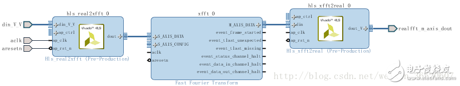
2. Add Hls_real2xfft and Hls_xfft2real both IP, and then connect HLS blocks and FFT block, connecting M_AXIS_DATA Interface din FFT module interfaces with the S_AXIS_DATA interface, and hls_xfft2real dout module interfaces with the FFT module here soon hls_real2xftt module, Finally, press Ctrl+A to create Hierarchy for all modules and name it RealFFT, and confirm that Move '3' selected blocks to new hierarchy is selected. 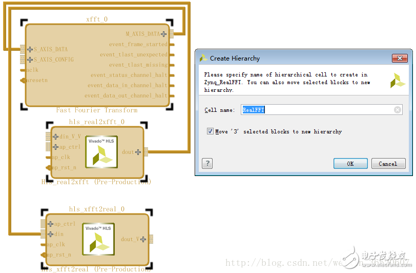
Click Project Manager here, right-click Zynq_ RealFFT and select Generate Output Products to generate the necessary source files. Right-click Zynq_RealFFT again to select Create HDL Wrapper. At this point, the top-level design becomes Zynq_ RealFFT _wrapper.v, then Generate Bitstream, and finally in the bitstream file. In the generated window, select Open Implemented Design and click OK.