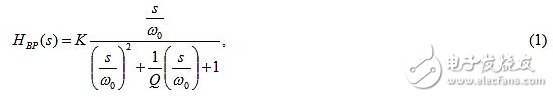
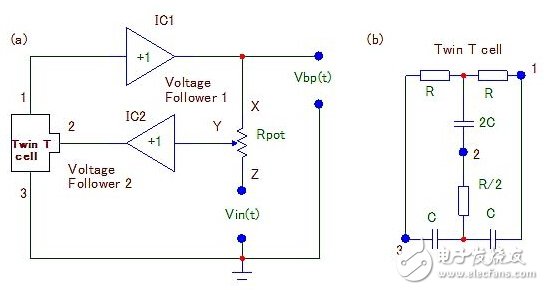
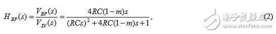
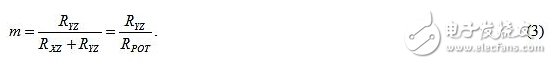
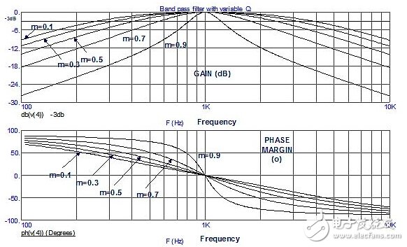
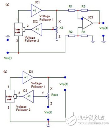
The design discussed in this paper can eliminate the differential circuit in the bandpass filter scheme, and the scheme properties provided by H.MarTInezetal. Bandpass filters (BPF) are widely used in applications where the passband is very narrow and any other frequency than the passband is attenuated. Equation (1) is a second-order bandpass transfer function of the bandpass filter: Where K represents a constant filter gain and Q represents the quality factor of the filter. In an article by H. MarTInezetal, a bandpass filter with an adjustable quality factor, a constant transmission coefficient at the resonant frequency point, and a three op amp design is described. The transfer function of such a filter conforms to equation (1), where K is inversely proportional to the quality factor Q. This bandpass filter with adjustable quality factor consists of a dual T unit and a differential circuit. The design discussed in this paper can eliminate the differential circuit in the bandpass filter scheme, and the scheme properties provided by H.MarTInezetal. The bandpass filter block diagram shown in Figure 1a has a voltage follower with IC1 and IC2 that can be implemented with a standard dual op amp and its inverting input connected to the op amp output. Figure 1: This active bandpass filter scheme (a) can change the quality factor while keeping the gain factor of the resonant frequency point constant. It is based on a dual T-cell (b) structure without a differential amplifier. The bandpass filter shown in Figure 1 is based on a double T-type structure (Figure 1b). The gain function formula of the filter designed according to Equation 2 (Reference 1) is: Where m is the positive feedback coefficient that is supplied to the double T unit (Fig. 1b) and is independent of frequency. The value of the quality factor depends on the position of the potentiometer RPOT. At the bottom of the potentiometer, the cursor shows that the quality factor Q of the filter is at a minimum. When the potentiometer is adjusted upwards, the quality factor increases. The positive feedback coefficient m is defined as: The resonant frequency of the active filter is: The quality factor Q of Equation 2 is: According to H.MarTInezetal.[1], the maximum gain AMAX always remains constant when ω = ω0, and is equal to 1 (0dB), independent of Q. When m=0, the quality factor is the smallest, the value is 1/4, and the rotor corresponding to the potentiometer is connected to the input terminal. The maximum gain is theoretically infinite, but in practical applications it is difficult to achieve a quality factor of 50 or more. The variation of Q ranges from 1 to 10 in typical applications. Figure 2 shows the Bode plot of the bandpass filter output VBP(s)/VIN(s) as the m value varies from 0.1 to 0.9. As can be seen from the figure, the frequency f0 is equal to 1 kHz. The modeling of the filter was performed using the "EpticalSoft" (ECAD) Micro-CAP9 circuit simulation program. Figure 2: Amplitude and phase Bode plot of the bandpass filter output VOUT(t). The figure shows the effect of changing the positive feedback coefficient m of a double T-type unit from 0.1 to 0.9. Our solution is realized by topological conversion of the original scheme of the notch filter composed of IC1 and IC2 by moving the ground of the input voltage source Vin(t). In this way, the recommended circuit excludes the additional differential circuit IC3 (Fig. 3b) and achieves similar results to Martinezetal (Fig. 3a). Figure 3: Both scenarios have the same transfer function. (a) - the solution provided by Martinezetal. (b) - our design.
Fire alarm cable
Rated Voltage: 300V/500V
Conductor: Class 1 or Class 2 copper
Insulation: Fire Retardant PVC
Shield: Aluminum Foil&Tinned Copper or N/A
Sheath: Fire Retardant PVC
Application: Those Fire Cable are used in high rise buildings,schools and educational institutions, hospitals, etc. for the connection with security systems like smoke detectors, emergency lighting, exit signboards and fire command center.
Fire Alarm Cable,Fireproof Cable,Fire Resistant Cable Types,Fireproof Wire Shenzhen Bendakang Cables Holding Co., Ltd , https://www.bdkcables.com