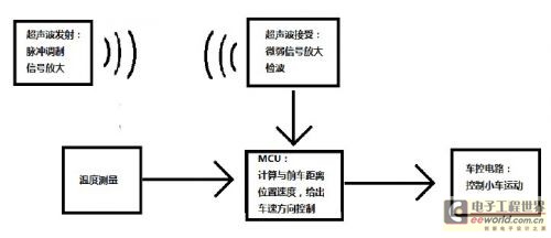
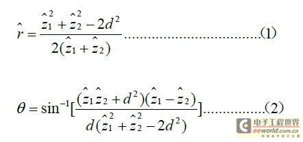
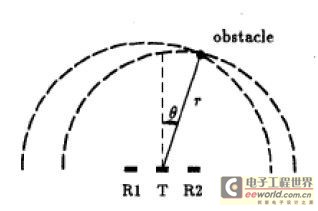
1 Introduction Ultrasonic sensors have been widely used due to their high measurement accuracy, fast response and low price. The traditional application method is that one transmitting head corresponds to one receiving head, and there are multiple transmitting heads corresponding to one receiving head. However, in practical applications, we found that if the surface of the obstacle is large (such as a wall), the ultrasonic Sensor can be used for accurate distance measurement, but if it is applied to the collision avoidance system of the car, the obstacle is column-shaped and the ultrasonic wave is emitted. The head has a certain scattering angle (left and right), so even if the obstacle is not in front of the car, the ultrasonic wave can detect the oblique forward echo, which brings difficulties and misleading to the intelligent control of the vehicle. In order to solve this problem, we propose A scheme using dual receiver heads and a set of specific control strategies from a practical perspective. 2 system structure flow design Our entire system needs to complete functions such as ranging, speed measurement, positioning, and control of trolley movement. The system consists of the following six parts: ultrasonic transmitting circuit, ultrasonic receiving circuit, signal processor, temperature measurement, and trolley control circuit. The system structure block diagram is shown in Figure 1: Figure 1: System block diagram The 40k square wave is generated by the single chip microcomputer, and after being amplified, the ultrasonic sensor emitting head is driven to emit ultrasonic waves, which are captured by the receiving end after being reflected by the front object, and the calculation of the capturing time of the two receiving heads and the addition of temperature compensation are performed to determine the final front. The direction and distance of the car, and then calculate the relative speed of the preceding vehicle by the difference with the previous data. Finally, the three parameters of speed, distance and position are used for intelligent control to control the turning or slowing down of the car. The specific hardware components are: MCU adopts AT89S52 single-chip microcomputer, P1.0 port outputs 40K square wave signal required by ultrasonic transducer, and drives sensor after inverter 7404. In order to make ultrasonic wave farther, we have connected The three transmitting heads use the external interrupt 0 to monitor the return signal output by the ultrasonic receiving circuit. The echo detection adopts the infrared detecting integrated chip CX20106. The display circuit adopts a simple 4-digit common-yang LED digital tube, and the broken code uses 74LS244. 8550 driver. The temperature measurement section uses the 18B20 to measure the current ambient temperature to determine the speed at which the ultrasonic wave propagates. 3 MCU algorithm control 3.1 Distance calculation and orientation judgment The single-chip microcomputer can calculate the time between transmitting and receiving the ultrasonic wave, and according to the actual temperature measurement of the temperature measuring system, find the sound velocity at the corresponding temperature, and calculate the distance of the reflector from the two receiving ends. Theoretically, the spatial position of the object can be directly derived mathematically from the above two data (as shown in Figure 2 and Equations 1 and 2). Figure 2 Ultrasonic sensor spatial orientation Where d is the distance between R1 and R2, and z1 and z2 are the distances from the object to each receiving end. If this calculation is too complicated, the ordinary single-chip processing will take more time, so we propose a distance based on the calculation. The method of roughly determining the position of an object. Generally speaking, the car only cares about the object in front of the car. We set a distance parameter l to represent the horizontal distance between the front obstacle and the car, and then set a distance parameter h, which represents the vertical distance between the front obstacle and the car. We can derive the relationship between h, l, d and z2-z1 from the following relationship (Equation 3 - Equation 6). Gear sensor has been widely used in the automotive and industrial field, which is important to the measurement of velocity, angel, angular velocity, direction of rotation. Gear Sensor,Custom Gear Sensor,Gear Sensor 3 Pins,Good Gear Sensor Yuheng Optics Co., Ltd.(Changchun) , https://www.yhencoder.com

