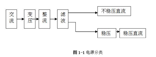
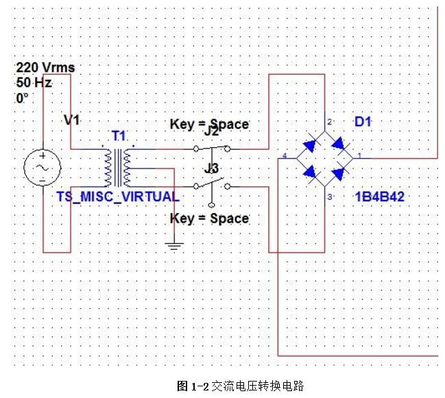
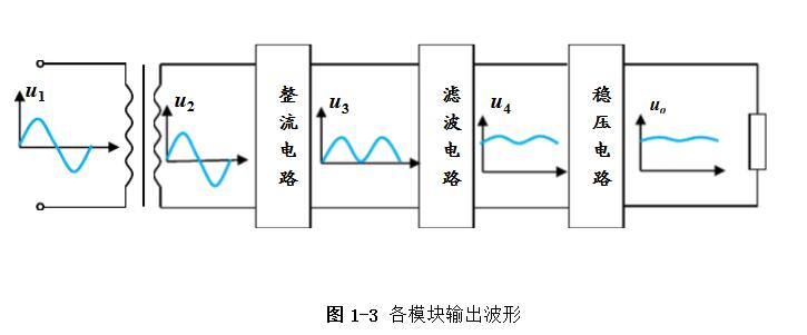
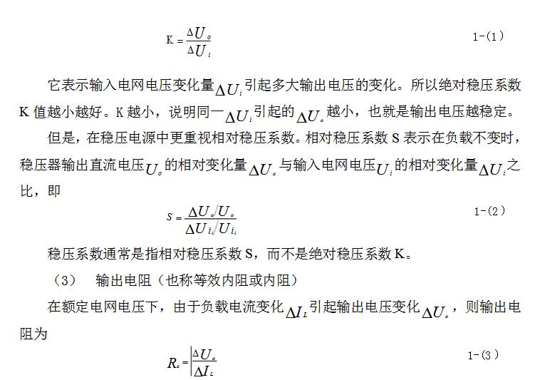
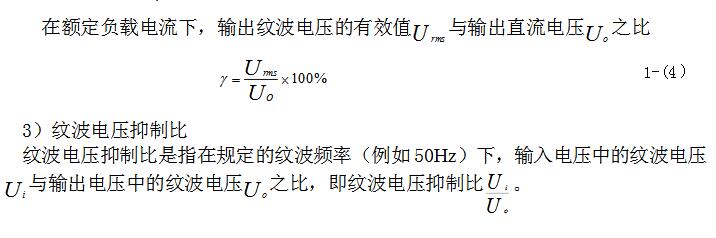
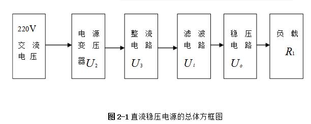
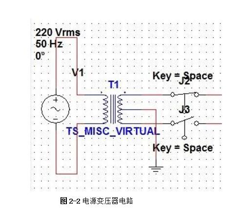
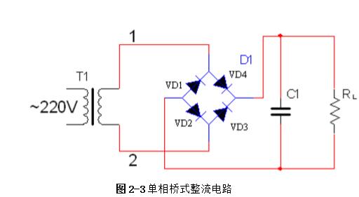
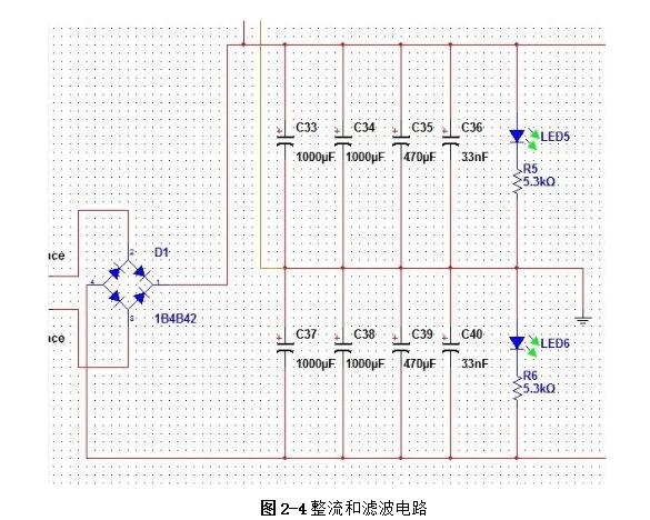
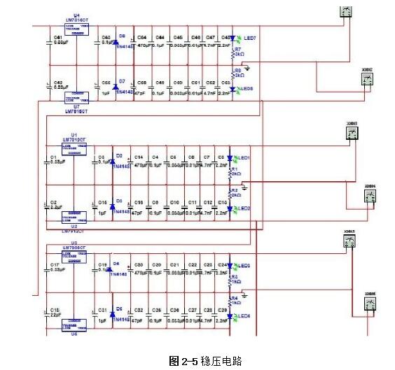
Linear regulated power supply refers to the DC stabilized power supply when the regulating tube works in a linear state. It is a power conversion circuit and an important part of the electronic system. Its function is mainly to provide the electronic circuit with the power it needs. Electronic equipment typically requires a voltage-stabilized DC power supply to power the load. Linear regulated power supplies are widely used in electronic circuits. Although various new types of voltage regulator circuits are emerging, linear regulated power supplies are always irreplaceable. 1, the working principle of ordinary power Now with the rapid development of electronic technology, the application fields of electronic systems have become more and more extensive, and the types of electronic devices are gradually updating and increasing. The relationship between electronic devices and people's daily work and life is also increasingly close. . Any electronic device is inseparable from a safe and effective power source, which is the power source of all power electronic devices, so it is aptly called the "heart of the circuit." In today's life, various high-tech products are increasingly demanding the technical performance indicators of power supplies. Power supplies can be divided into AC and DC power supplies, which are an integral part of any electronic device. DC power can be divided into two categories [8], that is: one type can directly supply DC current or voltage, such as batteries, batteries, solar cells, silicon photovoltaic cells, bio-batteries, etc.; the other is the ability to convert AC power In order to achieve the required stable DC current or voltage, such conversion circuits are collectively referred to as DC regulated power supplies. A large number of semiconductor devices are used in the circuits of modern electronic devices, which typically require a DC power supply of a few volts to several tens of volts in order to obtain the energy necessary for their normal operation. The DC stabilized power supplies used in modern electronic equipment are mainly divided into two categories: linear regulated power supplies and switching regulated power supplies. The linear regulated power supply is also known as the DC linear regulated power supply. Its voltage regulation performance is very good, and the output ripple is small. The disadvantage is that it requires the use of a power frequency transformer with a large volume and weight, and the stability efficiency is relatively low. . Switching regulated power supplies can be divided into several types according to different classification methods. According to whether the output is adjusted by other components such as adjustment elements (switching elements), the isolation can be divided into two types: non-isolated type and isolated type; according to the excitation mode of the switching element, it can be divided into self-excitation and his excitation. According to the input of the power supply, it can be divided into AC/DC and DC/DC; according to the connection form of the switching elements, it can be divided into two types: tandem type and side-by-side type. Its advantages are high efficiency, small size and light weight, but there are a series of shortcomings such as complicated circuit structure and difficult maintenance technology. The cost of both switching power supplies and linear power supplies increases as their output power increases, but the growth rates vary. In general, the cost of a linear power supply is relatively low when the output power is small. However, when the linear power supply cost is at a certain output power point, it is higher than the switching power supply, which is called the cost reversal point. The development direction of DC stabilized power supply: intelligent, digital, modular, green [11]. At the end of the 20th century, the birth of various active filters and active compensators also laid the foundation for the mass production of various green DC regulated power products in the 21st century. The linear regulated power supply refers to the DC stabilized power supply whose regulating tube works in a linear state. It is a power conversion circuit and is an important part of the electronic system. Its function is to provide the electronic circuit with the power it needs. After accessing 220V/50Hz mains, the 220V AC high voltage is converted to a low voltage output to the rectifier bridge through the transformer. After the rectification of the rectifier bridge, the DC motor with large pulsation is output and connected to the filter circuit. Reusing the characteristics of the voltage across the capacitor of the energy storage element can not be abrupt, filtering out the AC component in the output voltage of the rectifier circuit, retaining its DC component, and finally obtaining a smooth output voltage. (1) Grid adjustment rate It indicates the relative change in the output voltage of the regulated power supply when the input grid voltage changes by ±10% from the rated value, and is sometimes expressed in absolute value. Generally, the grid regulation rate of the regulated power supply is equal to or less than 1%, 0.1%, or even 0.01%. (2) Voltage regulation coefficient The voltage regulation coefficient has two kinds of absolute voltage regulation coefficient and relative voltage regulation coefficient. The absolute voltage regulation coefficient indicates that the load is constant. (4) Ripple voltage 1) Maximum ripple voltage The absolute value of the ripple (including noise) of the output voltage at rated output voltage and load current, usually expressed as peak-to-peak or rms. 2) Ripple coefficient γ 1. Overall block diagram of DC regulated power supply 2, the design of the power supply module circuit 2.1, power transformer The power transformer is a step-down transformer that converts the AC voltage of the 220V/Hz grid into a low AC voltage that meets the needs and sends it to the rectifier circuit. The transformer's transformation ratio is the ratio of the primary voltage to the secondary voltage, determined by the voltage output from the secondary side of the transformer. The main parameters of the transformer are: 1 Transforming ratio: The transformer's transformation ratio is the ratio of the primary voltage to the secondary voltage. 2 Rated power: It is the output power of the transformer that can work continuously at the specified frequency and voltage without exceeding the specified temperature rise. 3 Efficiency: It is the ratio of output power to input power, which reflects the loss of the transformer itself. 4 No-load current: When the transformer is under no-load under the working voltage (secondary current is zero), the current flowing through the primary coil is called no-load current. Transformers with large no-load currents have large losses and low efficiency. 5 Insulation resistance and electric strength: Insulation resistance refers to the resistance between the transformer coils, between the coil and the core and between the leads. The electric strength is the voltage that the transformer can withstand within a specified time. It is an important parameter for the safe operation of the transformer, especially the power transformer. The function of the power transformer Tr is to convert the AC voltage of the 220V grid into the rectification and filtering circuit. 2.2, rectifier circuit The rectifier circuit converts the AC voltage into a pulsating DC voltage. The filter circuit filters out the large ripple component and outputs a DC voltage with a small ripple. Commonly used rectification and filtering circuits include single-phase half-wave rectification filtering and bridge rectification filtering. Half-wave rectification: Using the unidirectional conductivity of the diode, only the positive voltage portion of the AC component is output, the circuit is very simple and easy, and the number of diodes used is also small. However, since it utilizes a half cycle of the AC voltage, the output voltage is low, the AC component is large, and the efficiency is low. Therefore, this circuit is only suitable for places where the rectified current is small and the pulsation requirements are not very high. Single-phase bridge rectifier circuit: consists of four diodes, the principle of which is to ensure that the direction of the voltage and current on the load does not change during the entire period of the secondary voltage of the transformer. It realizes a full-wave rectification circuit, which fully utilizes the negative half cycle of the secondary side output voltage. Therefore, when the rms voltage of the secondary side of the transformer is the same, the average value of the output voltage is twice that of the half-wave rectifier circuit. Therefore, considering this, the circuit design uses a single-phase bridge rectifier circuit. When the "1" terminal of the transformer is positive and the "2" terminal is negative, the diodes VD2 and VD4 are subjected to a forward voltage and turned on, and VD1 and VD3 are subjected to a reverse voltage and are turned off. At this time, the "1" end of the transformer flows through the RL through VD4, and then returns to the "2" end through VD2. When the "1" terminal is negative and the "2" terminal is positive, the diodes VD1 and VD3 are turned on, VD2 and VD4 are turned off, and the current flows from the "2" terminal through the VD3 through the RL, and then returns to the "1" terminal through the VD1. . 2.3, the filter circuit The filter circuit can filter out most of the AC components in the output voltage of the rectifier circuit, thereby obtaining a relatively smooth DC voltage. This circuit selects a capacitor filter circuit to meet its requirements. Each filter capacitor C must satisfy 2/) 5~3 (*TCRL=, where T is the period of the input AC signal, and RL is the equivalent load resistance of the rectifier filter circuit. 2.4, voltage regulator circuit The function of the voltage regulator circuit is to ensure that the DC voltage of its output is stable and does not change with changes in the AC grid voltage and load. It regulates the change of the load current by adjusting the current flowing through the Zener itself, and cooperates with the current limiting resistor to convert the current change into a voltage change to adapt to the fluctuation of the grid voltage. Commonly used integrated regulators are fixed three-terminal regulators and adjustable three-terminal regulators. This circuit requires an output of ±5V/1A, ±12V /1A and ±15V/1A. Therefore, the fixed three-terminal regulator LM7805CT, LM7905CT, LM7812CT, LM7912CT and LM7815CT, LM7915CT are used. The circuit design is very simple. The simplest circuit external components only need a fixed resistor and a potentiometer, and the operation is stable. The chip has transition, overheating and safe working area protection, and the maximum output current also meets the requirements. 3, circuit parameter calculation (2) Determine the voltage, current and power of the secondary side of the power transformer. The output current is less than 0.5A, and the output voltage is less than 12V. From the above analysis, a transformer with a secondary voltage of 16V and a power of 8W can be purchased. Select rectifier diode and filter capacitor. (3) Because the circuit form is bridge rectifier capacitor filtering, the filter capacitor value is obtained by the inverse peak voltage and operating current of each rectifier diode. (4) Selection of resistance DC stabilized power supply is an essential instrument for electronic experiments. In order for an electronic circuit to perform its functions, it must be powered by a DC power source. The DC stabilized power supply provides a continuously adjustable DC voltage for the electronic circuit, and should also have functions such as voltage and current display, alarm, and overcurrent protection. Also has many other functions, such as: can be used for the maintenance of various aging electronic equipment, such as aging PCB board, home appliances, various IT products, CCFL, lamp, etc.; suitable for automatic timing, power off, automatic The number of cycles of electronic aging components test; electrolytic capacitor pulse sophisticated; resistors, relays, motors and other tests sophisticated; machine veteran; electronic components performance test, routine test. DC stabilized power supply can also be widely used in national defense, scientific research, colleges and universities, laboratories, industrial and mining enterprises, electrolysis, electroplating, DC motors, charging equipment, etc. In addition, linear DC regulated power supplies can be used for mobile phone and computer maintenance. In the maintenance of the computer, the direct output of 5V and 12V is very reliable, and the adjustable output must be optimistic before connecting the circuit. Whether it can work or not is the most important. If the voltage is too high, it will be The circuit burns out, it's not good, and it can also trigger a series of security issues. In the process of repairing the mobile phone, because the change of the boot current needs to be observed in the judgment of the startup failure of the mobile phone, it is sufficient to use a current meter of up to 1A.
·Basic precautions
Do not put expensive oil into low-quality cartridges to avoid wastage. Most pre-filled oil cartridges have the so-called 510 thread. The oil cartridge screws onto a rechargeable battery. Some of these batteries have buttons and some heat up automatically when you pump the oil. Some batteries have multiple temperature settings and some heat up to a preset temperature; these features need to be known in advance.
·Cleaning notes
Use a suitable cleaning tool to clean them, such as activated charcoal or dried tea leaves in a used pipe to absorb the oil. It is important not to use alcohol or other boiling water to clean the pipe, and to wait until it has cooled down completely before cleaning. Otherwise, the hot stem will come into contact with the watery liquid and cause the mouthpiece tenon to loosen, thus shortening the life of the 510 cartridges.
This is what you should be aware of when using 510 cartridges. At the same time, when using 510 cartridges, there are still some vaping tips, for example, when using them, be careful not to suck too hard, will not produce smoke. When you inhale too hard, the smoke is sucked directly into your mouth and not atomized by the atomizer, so gently inhaling is more powerful and gives you a better vaping experience.
510 Cartridge Oem,Leakproof 510 Cartridge,510 Battery And Cartridges Oem,510 Cartridge Shenzhen MASON VAP Technology Co., Ltd. , https://www.disposablevapepenfactory.com