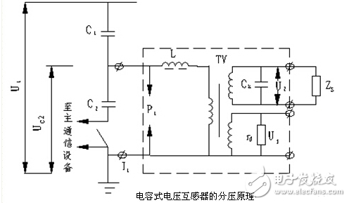
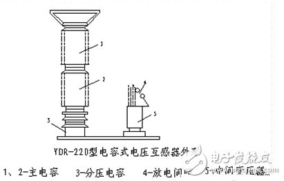
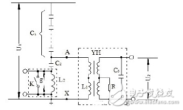
Capacitive voltage transformer (CVT) is a voltage transformer that is divided by series capacitors and then stepped down and isolated by electromagnetic transformers. It can be used as a voltage transformer for metering, relay protection, etc. Capacitive voltage transformers can also be used as carriers. The frequency is coupled to the transmission line for long-distance communication, remote measurement, selective line high frequency protection, remote control, teletype and the like. Therefore, compared with the conventional electromagnetic voltage transformer, the capacitive voltage transformer has many advantages in economy and safety in addition to preventing ferromagnetic resonance due to saturation of the voltage transformer core. The capacitive voltage transformer works by the voltage division principle of the capacitor. The basic structure includes a capacitor divider, an electromagnetic device, a protection device, etc., and some also have a carrier coupling device. (1) Capacitor voltage divider consisting of a high voltage capacitor C1 (main capacitor) and a series capacitor C2 (divider capacitor). The function of the voltage dividing capacitor C2 is to perform capacitance division. The voltage dividing capacitor can not be directly connected to the measuring instrument as the output terminal. Because the impedance of the secondary circuit is relatively small, it will affect its accuracy. Therefore, it must be depressurized by an electromagnetic voltage transformer and then connected to the secondary equipment such as the instrument. (2) The electromagnetic device is composed of an electromagnetic voltage transformer TV and a reactor L. Its function is to reduce the voltage across the voltage divider capacitor to the desired secondary voltage value. Since the voltage on the voltage dividing capacitor changes with the load, the reactor L is shunted in the voltage dividing circuit to compensate the internal impedance of the capacitor and stabilize the secondary voltage. (3) Protection device consisting of spark gaps P1 and P2 and damping resistor RD. 1) Spark gaps P1 and P2 are used to limit the overvoltage of the compensating reactor, electromagnetic voltage transformer and voltage divider. 2) Damping resistor RD to prevent continuous ferromagnetic resonance. The damping device is composed of a damping resistor and a saturable reactor connected in series, which is connected across the secondary winding. Under normal conditions, the damping device has a large impedance. When an overvoltage occurs due to ferromagnetic resonance, the reactor is saturated, and only the resistive load is left, so that the resonance energy is quickly lowered. Generally, a damping resistor of 400 to 600 W is installed on the secondary side of the 110-330 kV capacitive voltage transformer, but the long-term input limits the capacity of the voltage transformer, and also reduces the accuracy, which is uneconomical. Therefore, a method of installing a resonant damper on the secondary side of a 500-750 kV capacitive voltage transformer is also used, and an electronic switch circuit is also installed in the damper circuit, or a combination of the two methods. (4) A carrier coupling device is a line component capable of receiving a carrier signal, which can couple a carrier frequency to a transmission line for long-distance communication, remote telemetry, selective high-frequency protection, remote control, teletype, and the like. Connect it to the two ends of the grounding switch S, its impedance is small under the power frequency voltage, completely negligible, but its impedance is very large at the carrier frequency. If the carrier coupling device is not connected, the grounding switch S can be combined. on. The capacitive voltage transformer is essentially a capacitive voltage divider. For the sake of analysis, the capacitor string is divided into two parts, a main capacitor C1 and a voltage dividing capacitor C2, as shown in the upper left figure. Let the voltage on the primary side be U1, then on C2 The voltage is: UC2=C1/(C1+C2)U1=KU1 In the formula, K=C1/(C1+C2) is a partial pressure ratio, and the ratio of C1 to C2 is changed to obtain different partial pressure ratios. Since UC2 is proportional to the primary voltage U1, U1 can be obtained by measuring UC2, which is the working principle of the capacitive voltage transformer. The capacitive voltage transformer is stepped down by the intermediate transformer and then connected to the meter. As shown in the left figure below, the main reason is that the output of the capacitor divider cannot be directly connected to the meter. Otherwise, the secondary load impedance will affect its accuracy. The function of the protection gap is that when an abnormal overvoltage occurs on the voltage dividing capacitor, the gap first breaks down to protect the compensating reactor, the voltage dividing capacitor and the intermediate transformer from being damaged by overvoltage. Compared with electromagnetic voltage transformers, capacitive voltage transformers have the advantages of high impact insulation strength, simple manufacturing, light weight, small size, low cost, reliable operation, convenient maintenance and high-frequency carrier communication coupling capacitors. . The main disadvantage is that the error characteristics are worse than the electromagnetic voltage transformer, and the output capacity is small, and there are many factors affecting the error (such as temperature, frequency, etc.). At present, the accuracy of YDR-type capacitive voltage transformers manufactured in China has been increased to 0.5, and has been widely used in direct grounding systems with neutral points of 110KV and above. Capacitor voltage transformer wiring diagram : In a system where the neutral point is not grounded or the arc suppression coil is grounded, in order to measure the relative ground voltage, the PT primary winding must be connected in a star grounding manner. In the 3~60KV power grid, three single-phase three-winding voltage transformers or one three-phase five-column voltage transformer are usually used. It must be pointed out that this measurement cannot be made with a three-phase three-column voltage transformer. When a single-phase short-circuit occurs in the system, a zero-sequence current will pass through the three phases of the transformer, producing zero-sequence flux of equal magnitude and phase. In the three-phase three-column transformer, the zero-sequence flux can only form a closed magnetic circuit through the air gap with large reluctance and the iron casing, and the zero-sequence current is large, which causes the transformer winding to overheat or even damage the equipment. In the three-phase five-column voltage transformer, the zero-sequence magnetic flux can form a loop through the iron cores on both sides, and the magnetic resistance is small, so the zero-sequence current value is not large, and no damage is caused to the transformer. Pro Audio Speaker,18 Woofer Speaker,Subwoofer Loudspeaker,18 Inch Woofer Speaker Guangzhou Yuehang Audio Technology Co., Ltd , https://www.yhspeakers.com