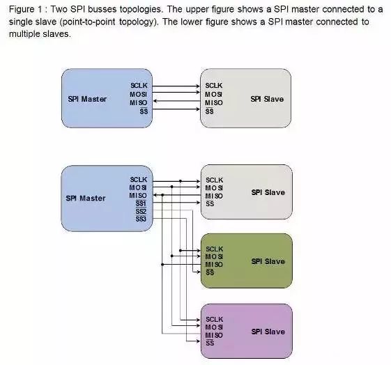
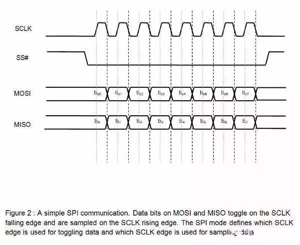
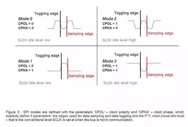
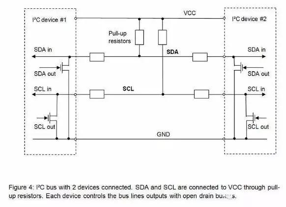
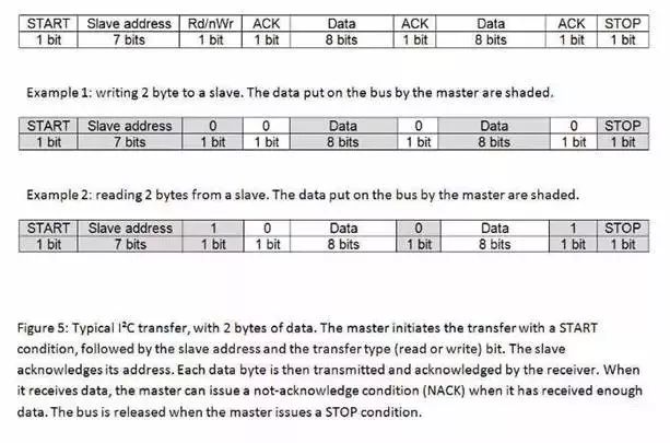
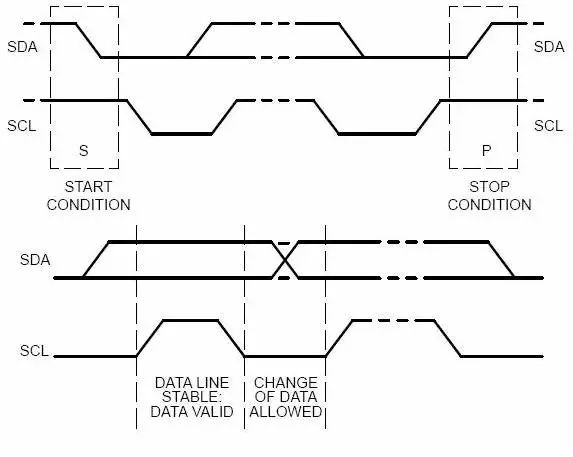
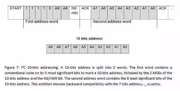
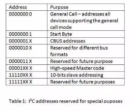
IIC vs SPI Today, in low-end digital communications applications, we can see IIC (Inter-Integrated Circuit) and SPI (Serial Peripheral Interface). The reason is that these two communication protocols are very suitable for short-distance inter-chip communication. Philips (for IIC) and Motorola (for SPI) have developed these two standard communication protocols for different backgrounds and market needs. IIC was developed in 1982 to provide an easier way to connect CPUs and peripheral chips in TV sets. The TV was one of the earliest embedded systems, and the original embedded system used memory-mapped I/O to interconnect microcontrollers and peripherals. To achieve memory mapping, the device must be connected in parallel with the data lines and address lines of the microcontroller. This method requires a large number of lines and additional address decoding chips when connecting multiple peripherals, which is inconvenient and costly. In order to save the microcontroller's pins and additional logic chips, making printed circuit boards simpler and less expensive, the Philips Laboratory in the Netherlands developed 'Inter-Integrated Circuit', IIC or IIC, one using only two The root line is connected to the bus protocol of all peripheral chips. The initial standard defined bus speed was 100kbps. After several revisions, it was mainly 400kbps in 1995 and 3.4Mbps in 1998. There are indications that the SPI bus was first introduced in 1979, and Motorola integrated the SPI bus into their first microcontroller chip that was modified from the 68000 microprocessor. The SPI bus is the external bus of the microcontroller's four wires (as opposed to the internal bus). Unlike IIC, SPI does not have a plain text standard. It is only a de facto standard. The implementation of communication operations is only a general abstract description. The chip manufacturer and the driver developer communicate the details through data sheets and application notes. SPI For experienced digital electronics engineers, interconnecting two digital devices with SPI is fairly straightforward. SPI is a four-signal line protocol (pictured): SCLK: Serial Clock (output from master); MOSI; SIMO: Master Output, Slave Input (output from master); MISO; SOMI: Master Input, Slave Output (output from slave); SS: Slave Select (active low, outputfrom master). SPI is a [single-master] communication protocol, which means that only one central device in the bus can initiate communication. When the SPI master wants to read/write [slave], it first pulls down the SS line corresponding to [slave] (SS is active low), then starts sending the working pulse to the clock line, at the corresponding pulse time. On the [master device] sends the signal to the MOSI to achieve "write", while the MISO can be sampled to achieve "read", as shown below: The SPI has four modes of operation - Mode 0, Mode 1, Mode 2, and Mode 3. The difference is that it defines which edge of the clock pulse to toggle the output signal, which edge samples the input signal, and the clock. The stable level value of the pulse (that is, whether the clock signal is high or low when it is invalid). Each mode is characterized by a pair of parameters called clock polarity CPOL and clock phase CPHA. [Master and slave devices] must use the same operating parameters - SCLK, CPOL, and CPHA - in order to function properly. If there are multiple [slave devices] and they use different operating parameters, then [master] must reconfigure these parameters between reads and writes [slave]. The main content of the above SPI bus protocol. The SPI does not specify the maximum transmission rate, there is no address scheme; the SPI does not specify a communication response mechanism, and no flow control rules are specified. In fact, the SPI [master device] does not even know if the specified [slave device] exists. These communication controls must be implemented by themselves outside the SPI protocol. For example, to connect a [command-response control type] decoder chip with SPI, a more advanced communication protocol must be implemented on the basis of SPI. SPI does not care about the electrical characteristics of the physical interface, such as the standard voltage of the signal. Initially, most SPI applications used intermittent clock pulses and transmitted data in bytes, but there are now many variants that implement continuous time pulses and data frames of any length. IIC is different from SPI single master device. IIC is the bus of multi-master device. IIC has no physical chip selection signal line. There is no arbitration logic circuit. Only two signal lines are used - 'serial data' (SDA) and 'serial clock. ' (SCL). The IIC Agreement states: First, each IIC device has a unique seven-digit device address; Second, the data frame size is 8 bits of bytes; Third, some of the data bits in the data (frame) are used to control the start, stop, direction (read and write) and response mechanisms of the communication. The IIC data transfer rates are standard mode (100 kbps), fast mode (400 kbps), and high speed mode (3.4 Mbps). Other variants implement low speed mode (10 kbps) and fast + mode (1 Mbps). In physical implementation, the IIC bus consists of two signal lines and one ground line. Both signal lines are transmitted in both directions, refer to the figure below. The IIC protocol standard stipulates that the device that initiates communication is called the master device. After the master device initiates one communication, the other devices are slave devices. The IIC communication process is roughly as follows. First, the master sends a START signal, which is like shouting at all other devices: Please pay attention! The other device then starts listening to the bus in preparation for receiving data. Next, the master device sends a 7-bit device address plus one bit of read and write data frames. After the device receives the data, it compares the address itself to the target device. If the comparison does not match, the device enters a wait state and waits for the STOP signal to arrive; if the match matches, the device sends an acknowledgement signal, ACKNOWLEDGE. When the master device receives a response, it starts transmitting or receiving data. The data frame size is 8 bits, followed by a one-bit response signal. The master device sends data and the slave device answers; instead, the master device receives data and the master device answers. When the data transfer is completed, the master device sends a STOP signal to announce the release of the bus to other devices, and the other devices return to the initial state. Based on the physical structure of the IIC bus, the START and STOP signals on the bus must be unique. In addition, the IIC bus standard stipulates that the data conversion of the SDA line must be in the low period of the SCL line. During the high period of the SCL line, the upper data of the SDA line is stable. In physical implementation, both the SCL line and the SDA line are open-drain, with a pull-up resistor plus a voltage source. When the line is grounded, the line is logic 0. When the line is released and the line is idle, the line is logic 1. Based on these characteristics, the operation of the bus by the IIC device only "grounds the line" - output logic 0. The IIC bus design uses only two lines, but it is quite elegant to achieve seamless communication between any number of devices. Let's imagine what happens if there are two devices sending information to the SCL line and the SDA line at the same time. Based on the design of the IIC bus, level conflicts are unlikely to occur on the line. If a device sends a logic 0 and the other sends a logic 1, then the line sees only logic 0. That is to say, if a level conflict occurs, the logic 0 is always "winner". The physical structure of the bus also allows the master to read data while writing data to the bus. This way, any device can detect the occurrence of a conflict. When the two masters competed for the bus, the "winner" did not know that the competition occurred. Only the "loser" found the conflict - when it wrote a logic 1, but read 0 - and exited the competition. 10-bit device address Any IIC device has a 7-bit address. In theory, there are only 127 different IIC devices in reality. In fact, there are far more types of IIC devices than this one, and the probability of an IIC device with the same address on a bus is quite high. To overcome this limitation, many devices use dual addresses—external configuration pins. The IIC standard also foresees this limitation and proposes a 10-bit address scheme. The 10-bit address scheme has two effects on the IIC protocol: First, the address frame is two bytes long, and the original one is one byte; Second, the first five most significant bits of the first byte are used as the 10-bit address identifier, and the convention is "11110". In addition to the 10-digit address identifier, the standard also reserves some address codes for other purposes, as shown in the following table: Clock stretching In IIC communication, the master determines the clock speed. Because the clock signal is explicitly issued by the master device. However, when the slave device cannot keep up with the speed of the master device, the slave device needs a mechanism to request the master device to be slower. This mechanism is called clock stretching, and based on the specificity of the I2C structure, this mechanism is implemented. When the slave device needs to reduce the speed of the transmission, it can press the clock line to force the master device to enter the wait state until the slave device releases the clock line, and the communication continues. High speed mode In principle, using a pull-up resistor to set a logic 1 limits the maximum transfer speed of the bus. Speed ​​is one of the factors limiting bus applications. This also explains why high speed mode (3.4 Mbps) is introduced. Before initiating a high-speed mode transmission, the master must first issue a specific "High Speed ​​Master" signal in low-speed mode (such as fast mode). In order to shorten the signal period and increase the bus speed, the high speed mode must use an additional I/O buffer. In addition, bus arbitration can be masked out in high speed mode. Please refer to the bus standard documentation for more information. IIC vs SPI: Which is the winner? Let's compare some key points of IIC and SPI: First, the bus topology/signal routing/hardware resource consumption IIC requires only two signal lines, while the standard SPI has at least four signals. If there are multiple slave devices, the signal needs more. Some SPI variants use only three wires - SCLK, SS and bidirectional MISO/MOSI, but the SS wire is still one-to-one with the slave device. In addition, if the SPI is to implement a multi-master architecture, the bus system requires additional logic and circuitry. The only problem with building a system bus with IIC is the limited 7-bit address space, but the new standard for this problem has been solved - using a 10-bit address. From the first point of view, IIC is an obvious big winner. Second, data throughput / transmission speed If high-speed data transmission must be used in applications, SPI is an inevitable choice. Because SPI is full duplex, IIC is not. The SPI does not define a speed limit, and a typical implementation can typically reach or exceed 10 Mbps. The highest speed of the IIC is also fast + mode (1 Mbps) and high speed mode (3.4 Mbps). The latter mode requires additional I/O buffers, which is not always easy to implement. Third, the elegant IIC is often said to be more elegant in SPI. To be fair, we are more inclined to think that both are equally elegant and robust. The elegance of the IIC lies in its features—multi-master arbitration and device routing with a very lightweight architecture. However, for the engineers used, it is more difficult to understand the bus structure, and the performance of the bus is not high. The advantage of SPI is that its structure is quite intuitive, easy to implement, and very scalable. The simplicity of SPI is not as elegant as it is because SPI is used to build a useful communication platform, and specific communication protocol software needs to be built on top of SPI. That is to say, in order to obtain the characteristics unique to SPI and not available in IIC - high-speed performance, engineers need to work harder. In addition, this custom work is completely free, which explains why SPI does not have an official standard. Both IIC and SPI provide excellent support for low-speed device communication. However, SPI is suitable for data streaming applications, while IIC is more suitable for multi-master applications of "byte devices". Summary In the digital communication protocol cluster, IIC and SPI are often referred to as "small" protocols, compared to Ethernet, USB, SATA, PCI-Express and other transmission speeds of hundreds of gigabytes per second. However, what we can't forget is what the purpose of the various buses is. The "big" protocol is used for communication between the entire system outside the system. The "small" protocol is used for communication between chips within the system, and there is no indication that the "big" protocol is necessary to replace the "small" protocol. The existence and popularity of IIC and SPI embodies the philosophy of “enough to useâ€. In response to the article, IIC and SPI are so popular, it is a must-have tool for any embedded engineer.
Mobile phones and earphones have become necessities in our lives. How many people feel restless when they don`t have a mobile phone around. The mobile phone gives us a great sense of security to a certain extent, and its additional earphones also have such a function. . Wear headphones when you don`t want to talk; when you don`t want to listen to others, you wear headphones; when you don`t want to be harassed in an unfamiliar environment, you can play your favorite songs, be happy or sad, and enjoy your little universe most comfortable. There are now a variety of earphones on the market for people to choose from. From the original wired earphones to the current wireless Bluetooth earphones, they are more and more in line with people's requirements, and the sound quality and noise reduction are also constantly improving.
If you want to get a sports headset (sports scene) or a true wireless tws true wireless Bluetooth headset, what you expect from him is that it has the ability to withstand the test of different environments, wear it steadily, and have a long battery life, or it may be out of the street. Appearance, excellent sound quality, stable connection, friends who have certain requirements for sound quality and low requirements for noise reduction. You can take a look our earbuds.
Tws Earphones,True Wireless Earphones,Good Sound Earbuds,Hifi Sound Headphones Shenzhen Focras Technology Co.,Ltd , https://www.focrass.com