With the needs of the development of contemporary society, almost everyone is using mobile phones, and mobile phones have become a daily necessities that we cannot do. In people's frequent use, it is gradually found that the mobile phone battery can not meet our requirements, and often after a period of use, there is a situation in which the charging time becomes short. A battery that has just been recharged has no power for a long time, so a repair device for repairing the battery of the mobile phone is born. This article refers to the address: http:// Second, the design principle (1) Introduction of mobile phone battery Nowadays, lithium-ion batteries are used in general mobile phone batteries. Mainly because the lithium ion battery is lithium ion (Li-Ion) and lithium polymer (Li-Pol), the battery has the characteristics of light weight, large capacity and small internal resistance. But we need to charge according to its characteristics, otherwise it will be very damaged, and its recharge number will be greatly discounted. Lithium ion needs to pay attention to not overcharge and overdischarge during charging. It has its own minimum voltage and maximum voltage. Generally, the lowest voltage is between 2.2V and 2.3V, and the highest voltage is between 4.2V and 4.3V, so we Care must be taken when setting up the circuit to set the discharge termination voltage and charge termination voltage. (2) Design ideas The design circuit is mainly divided into two stages of discharge and charging. A typical charger simply charges the battery, and the repairer has an additional discharge process. The discharge phase is mainly to completely discharge the residual power in the battery and bring its voltage to the discharge termination value. The discharge phase mainly pays attention to the setting of the discharge voltage termination value. If the battery is over-discharged, it will cause great damage to the battery. In the charging phase, we are different from the general charger, which uses a pulse signal whose frequency changes periodically to charge the battery. The main consideration is that the pulse signal can gradually activate the chemicals in the battery to make the battery reach the factory. Similarly, the charging voltage termination value cannot be exceeded during charging, and overcharging may cause permanent damage to the battery. Third, the production process (1) Design of the discharge circuit 1. Design requirements 1 The discharge current is generally 0.2 times the rated capacity of the battery. 2 The discharge termination voltage must be accurately understood to avoid damage to the battery due to overdischarge. 3 Start and stop the discharge in manual mode. 2, design points 1 When the battery is discharged to the end voltage, the discharge circuit should be automatically disconnected or automatically transferred to the charging state. 2 It is convenient to monitor the discharge working state. The following is a schematic diagram of the discharge circuit design: The drive circuit part can be composed of two relays to form a self-locking circuit. When the discharge is finished, the switch is automatically disconnected and transferred to the charging part. (two) the design of the charging circuit 1. Design indicators 1 Adjustable constant current charging, maximum charging current 500mA. 2 At the end of the discharge, it automatically switches to the constant current charging state. 3 When charging to the charge termination voltage, the constant current circuit stops working and the “end of charge†state is locked. 2, design points 1 Use the voltage comparator to monitor the battery voltage to ensure that the charge current is turned off and the “end of charge†state is locked when the charge termination voltage is reached. 2 automatic function and manual start and stop functions. The charging circuit is combined with the pulse signal to charge the circuit. The pulse signal here can be realized by a 555 timer, and three 555s are used to form a pulse signal whose frequency changes periodically. The circuit diagram is shown in the figure. The connection of the whole circuit needs to have a logical relationship, which can be realized by the NAND gate. In the design, we adopt the 4012 four-phase input NAND gate. (3) Design logic 1, the logical relationship of the discharge circuit The potential at point A is low at the time of discharge and high at the state of charge. At this point, we will record it for the time being. 2, the charging circuit logic relationship It can be seen that the potential at point B is low in the discharge state, and is high in the state of charge, which is the same as the potential at point A. From this we connect the two potentials to the input of the NAND gate. 3, the overall logical relationship The two points A and B and the pulse signal are connected to the input end of the NAND gate, and then the signal is output through a non-gate. In this way, a logical relationship can be formed. As shown in Table 1. Connected to both ends of the battery, you can use a switch TWH8778 to connect. Table 1: Logical relationship of output signals Fourth, summary The circuits and devices used in this design are common circuits for us. They are very helpful for current students in the electrical field. Through such electronic production, we can consolidate our expertise, enhance the understanding of each part of the circuit and the performance of each device. Instructions. The repair instrument for lithium-ion batteries is indispensable in the future development. Because of the environmental protection and energy-saving characteristics of lithium-ion batteries, it will be the focus of future development. Many household electrical appliances will gradually adopt lithium-ion batteries. In addition, the charger can be modified to charge nickel-cadmium batteries or nickel-metal hydride batteries, which can further expand its functions and leave a lot of room for thinking. D-sub Connector Contacts D-SUB coaxial contact,D-Sub Connectors Contacts,D-Sub Plug Connectors Contact,D-Sub Receptacle Connectors Contact ShenZhen Antenk Electronics Co,Ltd , https://www.antenk.com
Discharge circuit diagram 
Pulse signal circuit diagram 
Charging circuit logic diagram 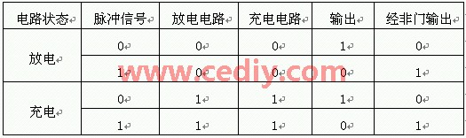
Other circuit parts, mainly power supply control part, can use rectification, filtering, and voltage regulation to convert the AC signal into the DC power supply we need. The charging current can be charged by a constant current source.
A D-sub connector is a form of connector commonly found in electronic and computer systems. It consists of a D shaped metal band and two or more parallel rows of either pin contacts (male) or socket contacts (female). D-sub connector contacts can vary in size, material, current rating, length and resistance.
The most common type of connector is the crimp contact. These are assembled by inserting a stripped wire end into the cavity at the rear of the contact. The cavity is then crushed using a crimp tool, gripping the contact to the wire.
What are D-sub connector contacts used for?
The D-sub connector contacts carry the signal from the source to the destination across the D–sub connection.
Types of D-sub connector contacts
Most D-sub connectors are supplied with contacts ready in place. Contacts can be replaced if damaged or if the application of the D-sub connector is to be changed from the original design specification.
High-current, high-voltage, or co-axial inserts require larger contacts. The material of the D-sub connector contact can be changed if the robustness or quality of the connection needs to be improved.
introduction